Injection Molding Residual Stress Prediction in Variable Wall Geometry
Polycarbonate parts with 2.0mm to 4.5mm wall steps generate 34 MPa thermal stresses; accurate 3D viscoelastic simulation prevents expensive re-cuts.


Mechanics
Predicting molecular orientation and volumetric contraction across variable cross sections requires separating flow-induced stress from thermal stress. As polymer melt enters a mold cavity, rapid shear deformation occurs against the chilled walls while the core remains hot and fluid. In uniform wall sections, this produces a symmetric shear profile that relaxes predictably during cooling.
Changing wall thickness breaks that equilibrium: as melt moves from a thin section into a thicker one, abrupt shifts in velocity gradient alter local shear, locking stretched polymer chains into the flow direction.

Coupled Viscoelastic and Thermal Stress Generation
Melt flowing through a mold cavity experiences steep shear gradients along frozen skin layers, where oriented polymer molecules store elastic energy. When cooling outpaces molecular relaxation, that energy stays locked in the polymer matrix as flow-induced residual stress. Thin sections produce high shear rates up to 10,000 inverse seconds, freezing molecules while still stretched.
Upon entering an adjacent thick section, the shear rate drops sharply, generating secondary eddies and concentrated stress along the transition radius.
Thermal residual stresses develop later during the packing and cooling phases. As the polymer cools below its glass transition or crystallization temperature, volumetric shrinkage occurs according to its Pressure-Volume-Temperature properties. In parts with variable wall thickness, thin sections freeze quickly under high packing pressure to form a dense shell, while thicker regions stay molten longer.
When the interior of a thick section solidifies, surrounding rigid walls constrain contraction, generating tensile stresses in the core and compressive stresses near the mold surface.
Polycarbonate parts featuring a 2.0 millimetre to 4.5 millimetre wall step generate localized internal tensile stresses up to 34 MPa under standard packing pressures.

Wall Thickness Transitions and Pressure Profiles
A stepped geometry interrupts the steady pressure drop found in uniform channels. Steep hydraulic pressure drops across narrow sections restrict the packing pressure reaching downstream thick areas. Once a thin section solidifies, hydraulic pressure transmission stops entirely, leaving the molten core in the thick section to cool without compensating polymer flow.
This uneven shrinkage locks in a permanent stress gradient across the wall step.
- Shear orientation stress uncoils polymer chains along frozen boundary layers, locking molecular extension into thin cross sections where rapid heat extraction prevents stress relaxation.
- Volumetric contraction imbalance arises from variable cooling rates across wall steps, producing localized density differentials between fully packed thin sections and under-packed thick cores.
- Packing pressure decay restricts mass transfer through solidified thin zones, leaving adjacent thick regions to solidify without adequate pressure compensation.
- Asymmetric layer freezing shifts the neutral thermal axis toward the colder mold half, inducing out-of-plane bending moments across the geometric transition.
Neglecting the interaction between flow shear stress and cross-sectional steps causes environmental stress cracking during downstream solvent cleaning.

Chill
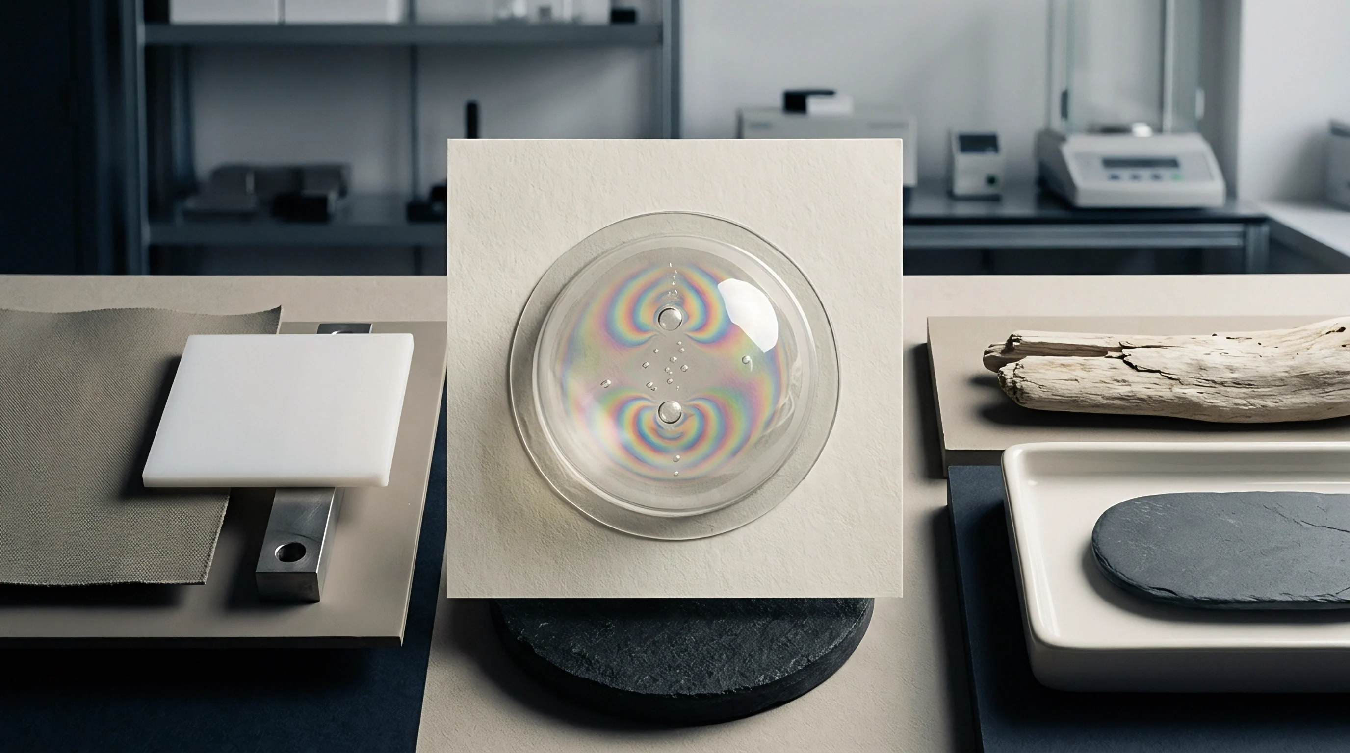
Temperature distribution across solidifying polymer melt determines how and where volumetric shrinkage occurs. Heat transfer inside the cavity depends primarily on conduction through the melt toward the cooled steel walls. Because polymers exhibit low thermal diffusivity ~ typically between 0.08 and 0.12 square millimetres per second ~ thick sections retain heat long after thin areas reach ejection temperature.
This uneven heat extraction generates deep thermal gradients across wall steps, shifting maximum tensile stress toward the geometric center of the thickest region.

Cooling Dynamics across Thickness Transitions
Heat extraction rates scale inversely with the square of wall thickness: a 4.0 millimetre wall section takes four times longer to reach ejection temperature than a 2.0 millimetre wall. Throughout that longer cooling period, the frozen thin section acts as a rigid boundary, constraining thermal contraction in the solidifying thick zone. The boundary between frozen walls and the molten core undergoes severe transverse shear stress.
Transient finite element calculations show that peak thermal stress develops near the internal transition radius during core solidification.
Unbalanced tool cooling compounds this stress state, as mold layouts often struggle to remove heat from core inserts located behind thick features. Higher steel temperatures on the core side delay skin formation, creating unequal skin thicknesses across the part profile. The neutral axis then shifts toward the colder cavity side, introducing a net bending moment that manifests as part distortion after ejection.
Thicker nominal wall sections freeze later, continuing to draw polymer mass from adjacent thin zones until gate freeze isolates the cavity.

Asymmetric Thermal Contraction Mechanics
Unequal heat removal between cavity and core mold halves pulls the neutral thermal axis off center. Although solidification progresses inward from both mold walls, unbalanced heat flux yields uneven skin growth. The layer solidifying against the warmer tool face experiences lower yield stress during cooling, allowing greater stress relaxation, while the colder mold face rapidly locks in high compressive stresses.
Upon ejection, these unbalanced internal stresses resolve into physical displacement, warping the part toward the hotter tool surface.
| Polymer Grade | Wall Step Ratio (Thin to Thick) | Peak Shear Stress (MPa) | Peak Thermal Tensile Stress (MPa) | Warpage Amplitude (mm) |
|---|---|---|---|---|
| Unfilled Polycarbonate (PC) | 1:2.0 (2.0mm to 4.0mm) | 18.4 | 28.5 | 1.42 |
| Unfilled Polycarbonate (PC) | 1:3.0 (1.5mm to 4.5mm) | 26.2 | 38.1 | 2.85 |
| Acrylonitrile Butadiene Styrene (ABS) | 1:2.0 (2.0mm to 4.0mm) | 12.1 | 19.8 | 0.88 |
| 30% Glass-Filled PBT (PBT-GF30) | 1:2.0 (2.0mm to 4.0mm) | 31.5 | 44.2 | 0.62 |
Placing cooling channels closer to thick wall sections balances cross-sectional solidification rates across asymmetric part profiles.


Solver
Numerical algorithms convert non-linear viscoelastic constitutive laws into predictive spatial stress fields. Standard midplane shell solvers lack the spatial resolution to capture three-dimensional stress gradients through thickness transitions. Accurate residual stress calculation requires fully three-dimensional finite element formulations that solve Navier-Stokes equations coupled with energy conservation and rheological constitutive equations.
Simulation engines use the Cross-WLF viscosity model to capture shear rate dependence and thermal sensitivity during the filling stage.

Does Mesh Density Control Boundary Stress Variance?
Resolving boundary element gradients across cross-sectional steps requires minimum layer counts to avoid shear truncation errors. Standard numerical solvers use tetrahedral or hexahedral meshes across variable wall geometries. Simulating stress distribution across a wall step demands at least ten to twelve element layers through the wall thickness.
Coarse meshes underpredict peak skin shear stresses by smoothing velocity gradients across transition zones. Fine boundary-layer meshing isolates high-gradient regions near mold walls, capturing local velocity changes as fluid transitions into thicker cavity regions.
Isotropic thermal shrinkage models fail to predict anisotropic distortion in fiber-reinforced polymers. When glass fibers pass through a wall step, sudden flow deceleration forces fibers to reorient perpendicular to the primary flow direction. The solver must calculate fiber orientation tensors across each element layer, applying orthotropic mechanical properties to the structural stress mesh.
Fiber orientation dictates local mechanical moduli, directly altering residual thermal stress magnitude.

Viscoelastic Constitutive Equations and Viscosity Models
Rheological models incorporate shear rate dependence and thermal relaxation spectrums to track frozen molecular alignment. Solvers utilize the Viscoelastic Leonov or Upper Convective Maxwell models to track the evolution of elastic strain tensors during processing. These models evaluate flow-induced stresses by tracking stress tensor relaxation throughout filling and packing.
Coupled thermomechanical solvers map these flow-induced stresses directly onto the structural mesh, adding them to thermal residual stresses calculated from Pressure-Volume-Temperature cooling tracks.
- Import target CAD geometry and assign anisotropic surface mesh elements along wall transition radii.
- Generate a minimum of twelve layers through the thickness direction across all variable step zones.
- Apply temperature-dependent Pressure-Volume-Temperature data coupled with viscoelastic Cross-WLF relaxation spectra.
- Execute non-isothermal flow solution to capture flow-induced shear orientation prior to gate freeze.
- Solve transient thermomechanical boundary conditions to calculate thermal residual stress distributions.
DIN 16742 Tolerance Group TG4 applies only when variable wall transitions maintain a taper angle below fifteen degrees across the flow length.
Whether non-isothermal viscoelastic solvers accurately capture stress relaxation during prolonged post-filling hold phases remains open to empirical debate.


Metrology
Physical measurement validates numerical simulations by isolating frozen-in stresses from post-molding environmental relaxation. High residual stresses reduce impact strength, accelerate chemical degradation, and induce dimensional drift over operational lifespans. Standard optical and mechanical test protocols establish empirical baseline stress fields across stepped geometries.
Destructive strain relief techniques and non-destructive optical techniques isolate stress components generated during processing.
Experimental Hole Drilling and Optical Birefringence
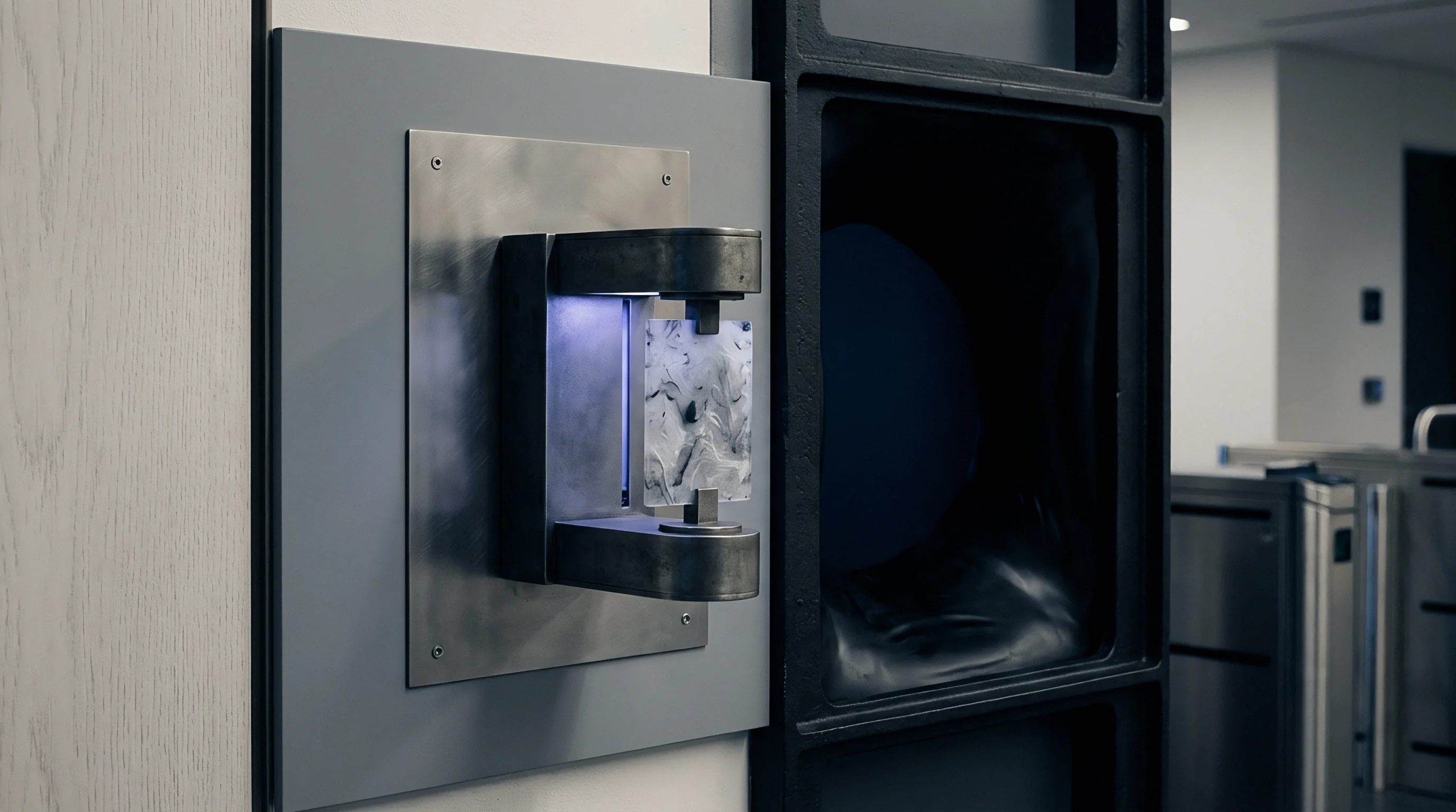
Sub-surface strain relief measurements execute through specialized strain gage rosettes bonded to sectioned samples. ASTM E837 defines the standard test method for determining residual stress profiles via incremental hole drilling. A high-speed air turbine drills a precise micro-hole through the part thickness in 0.05 millimetre increments.
Relieved surface strains are measured by the rosette gages and converted into principal stress distribution curves. This method reveals steep tensile stress peaks within the interior of thick wall sections adjacent to geometry steps.
Photoelasticity offers non-destructive visualization of stress field topology in transparent amorphous polymers. Polarized light passing through an injection-molded optical component undergoes double refraction proportional to internal principal stress differences. Fringe pattern density increases near wall thickness transitions, indicating concentrated stress gradients.
Calibrated optical polariscopes quantify light phase retardation, converting fringe orders into quantitative principal stress values across the component body.
| Measurement Protocol | Target Stress State | Destructive Status | Spatial Resolution | Thickness Limitation |
|---|---|---|---|---|
| ASTM E837 Hole Drilling | In-plane thermal and flow stress | Destructive | 0.05 mm depth steps | Maximum 5.0 mm depth |
| Optical Photoelasticity | Integrated flow birefringence | Non-destructive | Continuous 2D field | Transparent amorphous only |
| X-Ray Diffraction (XRD) | Crystalline phase lattice strain | Non-destructive | 0.01 mm surface spot | Surface layer ( |
| Layer Removal Method | Through-thickness stress profile | Destructive | 0.10 mm plane steps | No geometric limitation |

Physical Strain Gage Calibration and Deflection Mapping
Converting optical retardance into stress values demands accurate determination of the material photoelastic constant. Semi-crystalline polymers like polyamides require X-ray diffraction to evaluate lattice parameter distortion in crystalline lamellae. Combining optical measurement with mechanical sectioning maps frozen-in stress state evolution across variable geometry profiles.
- Photoelastic fringe counting maps continuous principal stress difference boundaries within transparent amorphous components exposed to polarized illumination.
- Incremental hole drilling records strain relief voltages at set depth intervals to calculate through-thickness stress profiles according to ASTM E837 formulas.
- Curvature deflections track out-of-plane part displacement following sequential layer removal to calculate internal stress distribution moments.
- X-ray diffraction analysis measures atomic lattice spacing shifts within semi-crystalline crystalline regions to isolate surface stress components.
Measured part distortion often originates from post-ejection handling rather than improper packing pressure.


Allowance
Translating residual stress fields into tooling geometry requires pre-deforming the mold cavity to counter calculated warpage vectors. Standard shrink allowances assume uniform volumetric contraction across the entire part layout. When variable wall geometry creates non-uniform stress distributions, applying a single global shrink percentage leads to dimensional failure.
Toolmakers must incorporate differential shrink values across wall step boundaries, modifying steel geometry to compensate for predicted thermal deflection.

Steel Compensation for Asymmetric Shrinkage
Toolmakers adjust core and cavity block dimensions to absorb out-of-plane distortion predicted by thermomechanical simulation. Modern CAD-to-tooling workflows invert calculated warpage vectors, generating modified surface meshes that serve as direct targets for CNC machining or EDM erosion. For a wall section stepping from 2.0 millimetres to 4.0 millimetres, local shrink allowances vary between 0.5 percent in thin zones and 1.2 percent in thick zones.
Over-compensating steel dimensions prevents costly secondary welding or metal-safe modifications during tool tryout phases.
High cavity pressures acting on asymmetric core details generate mechanical bending moments during injection. When gate location directs melt against one side of a thick core feature, lateral force imbalance displaces the core pin. This displacement alters local wall thickness, exacerbating thermal residual stress gradients.
Tool designers must evaluate core support mechanisms and sleeve tolerances under peak packing pressures up to 120 MPa.
Transient thermal gradients across asymmetric core cooling channels dominate out-of-plane distortion far more than volumetric shrinkage alone.

Tolerance Grades under Variable Thermal History
Standard precision classifications depend directly on cross-sectional uniformity across the parting line. DIN 16742 defines achievable production tolerances based on mold material, part size, and geometry variations. Components featuring variable wall steps exceeding a 1:1.5 ratio cannot hold narrow tolerance classes like TG3 or TG4 without specialized process controls.
Wall thickness variation forces part tolerances into wider TG6 or TG7 classifications due to inherent shrinkage unpredictability across transition boundaries.
- Transition radius criteria mandate a smooth taper angle below fifteen degrees between adjacent wall thicknesses to prevent localized shear stress spikes.
- Conformal cooling layout incorporates additive manufactured tool inserts with internal cooling channels following variable wall geometry profiles.
- Core sleeve support provides mechanical rigidity against side-action pressure differentials generated during asymmetric cavity filling.
- Ejection pin distribution balances mechanical push force against localized high-residual-stress areas to prevent ejection stress marks.
Applying ISO 20457 Clause 5.2 shifts dimension verification responsibility to post-conditioning hold periods, forcing dimensional sign-off forty-eight hours after ejection.


Settlement
Financially evaluating a tool design involves accounting for production cycle delays caused by thick wall sections. The thickest feature in a variable wall moulding dictates the minimum required cooling time before part ejection. Secondary stress relaxation continues inside the closed tool until the part develops sufficient structural rigidity to withstand ejection forces.
Running a mold with an uncompensated 4.0 millimetre wall section alongside 2.0 millimetre nominal walls extends cycle time by up to 12 seconds per shot.

Cycle Time Penalties in Variable Wall Geometries
Extended cooling phases driven by thick features increase machine hour charges over the entire production run. Hourly press rates scale directly with machine tonnage. Operating a 300-tonne machine at a 38-second cycle rate instead of an optimized 26-second cycle rate adds significant piece-price penalties over a 100,000-unit annual contract.
Parts rejected during automated assembly due to residual-stress-induced distortion create scrap costs that destroy production margins.
Unpredicted part distortion during initial tool trials triggers expensive Engineering Change Orders (ECOs). Re-machining mold steel via EDM or CNC recuts costs between 3,000 and 15,000 USD per cavity iteration, depending on tool complexity. If stress fields force toolmakers to alter gate locations or relocate cooling channels, tool modification costs escalate rapidly, delaying start-of-production milestones by weeks.

Tooling Amortization and Modification Costs
Iterative steel re-cuts add significant expense to mold building budgets when unpredicted warpage exceeds drawing limits. Amortizing these unexpected tooling modification expenses over low-volume production runs significantly increases unit costs. Upfront simulation investments that accurately predict variable wall residual stresses reduce trial iterations from four tool modifications down to a single fine-tuning cut.
Minimizing tool modification loops protects overall project profitability.
Contractual clarity on tool modification allowances protects tooling budgets when variable wall features demand unexpected cavity EDM re-machining.