Designing Micro Venting Topography for Laser Textured Plastic Injection Molds
Integrating femtosecond laser micro-venting channels directly into mold texture topography eliminates gas burns and fill hesitation without causing resin flash.


Void
In high-precision injection molding, laser-textured cavity surfaces introduce complex micro-scale topographies to scatter light and produce fine matte finishes. That intricate surface texture changes how air moves as the mold fills. As molten polymer advances toward the cavity walls, atmospheric air gets trapped inside sub-micron pockets and micro-grooves.
Standard parting-line vents cannot bleed gas trapped in isolated surface features far from the split line, where it undergoes severe compression as the melt front approaches at speeds above 200 millimeters per second.
Pressure inside unvented micro-pockets rises following ideal gas behavior as the volume rapidly shrinks.

Melt Front Evacuation Physics
Gas evacuation across micro-textured cavities depends on fluid displacement driven by the pressure gradient at the melt front. When advancing resin seals around the edge of a textured zone, compressed air creates a localized counter-pressure barrier. This gas cushion keeps the polymer from filling texture valleys completely, forcing the melt to bridge over them and leaving dull spots, uneven gloss, and visible flow lines on the part.
Under laminar flow, the resistance of gas escaping through micro-channels scales inversely with the fourth power of the channel hydraulic diameter. Standard laser texturing creates peak-to-valley heights between 5 and 50 micrometers. When those grooves double as aesthetic finishes and exhaust paths, polymer pressure compresses their cross-sections, while high injection speeds exacerbate adiabatic heating.

Thermal Degradation from Trapped Atmosphere
Due to the fast injection speeds typical of thin-wall automotive and electronic parts, trapped air compresses under near-adiabatic conditions. Local temperatures in compressed gas pockets quickly exceed 400 degrees Celsius once cavity pressure reaches 800 bar.
Gas pocket temperatures exceeding 450 degrees Celsius during a 0.15 second packing phase cause immediate local pyrolytic degradation of polycarbonate resins.
Polymer chains exposed to extreme thermal spikes undergo scission, releasing volatile organic compounds that react with oxygen in the trapped pocket. This diesel effect leaves dark carbonaceous deposits on tool steel ~ commonly known as mold burn. Over extended production runs, these acidic combustion products pit polished steel surfaces and trigger unscheduled downtime for cleaning.
Omitting micro-cavity venting from laser texturing programs leads to short shots, high scrap rates, and severe gloss variation, forcing costly tool modifications after the steel has already been hardened.
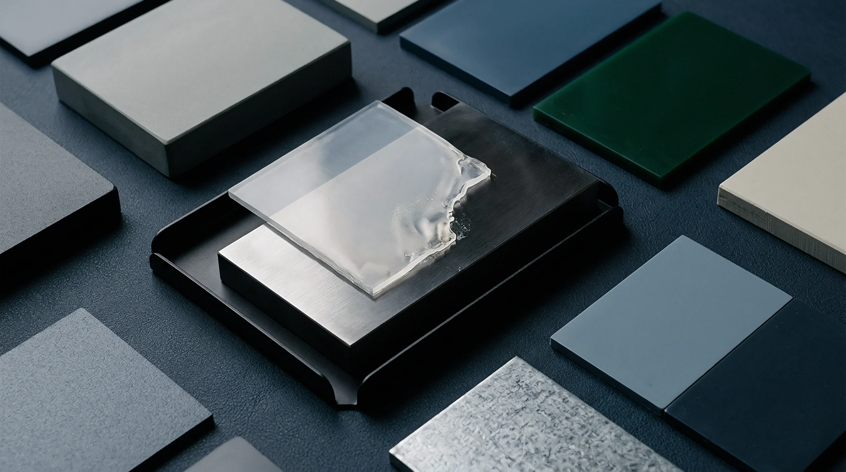
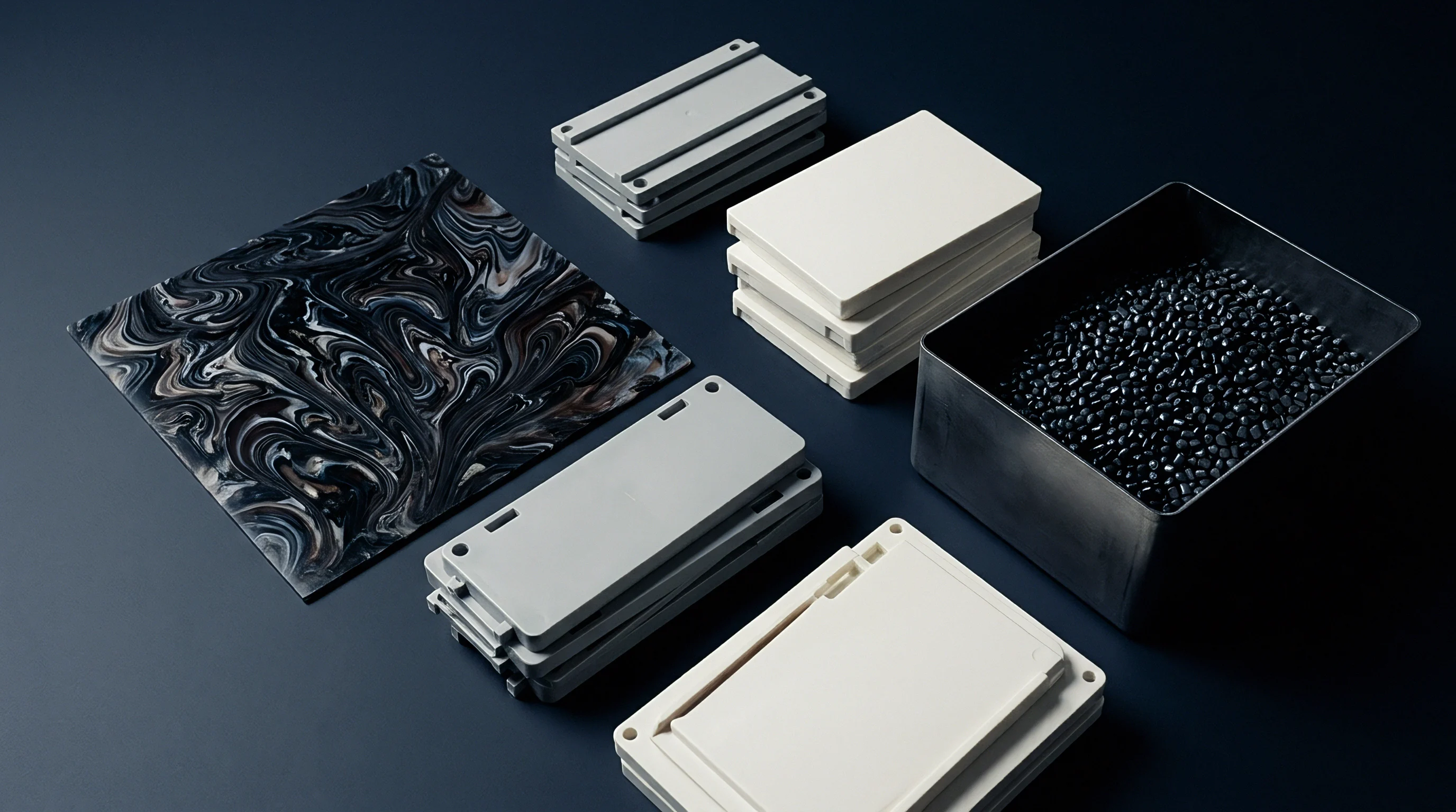
Ablation
Direct laser micro-machining relies on focused optical energy to vaporize tool steel with sub-micron precision, carving visual grain patterns and functional micro-venting topography in a single setup. Ultra-short pulse lasers operating in femtosecond and picosecond regimes process hardened steels like 1.2343 (H13) and 1.2083 (420 stainless) without leaving heat-affected zones or recast layers that could block narrow exhaust paths. Coordinating five-axis laser scanning heads with digital CAD models allows toolmakers to cut directional venting channels directly into the texture geometry.
Because laser ablation works optically, it exerts no mechanical cutter pressure on the tool.
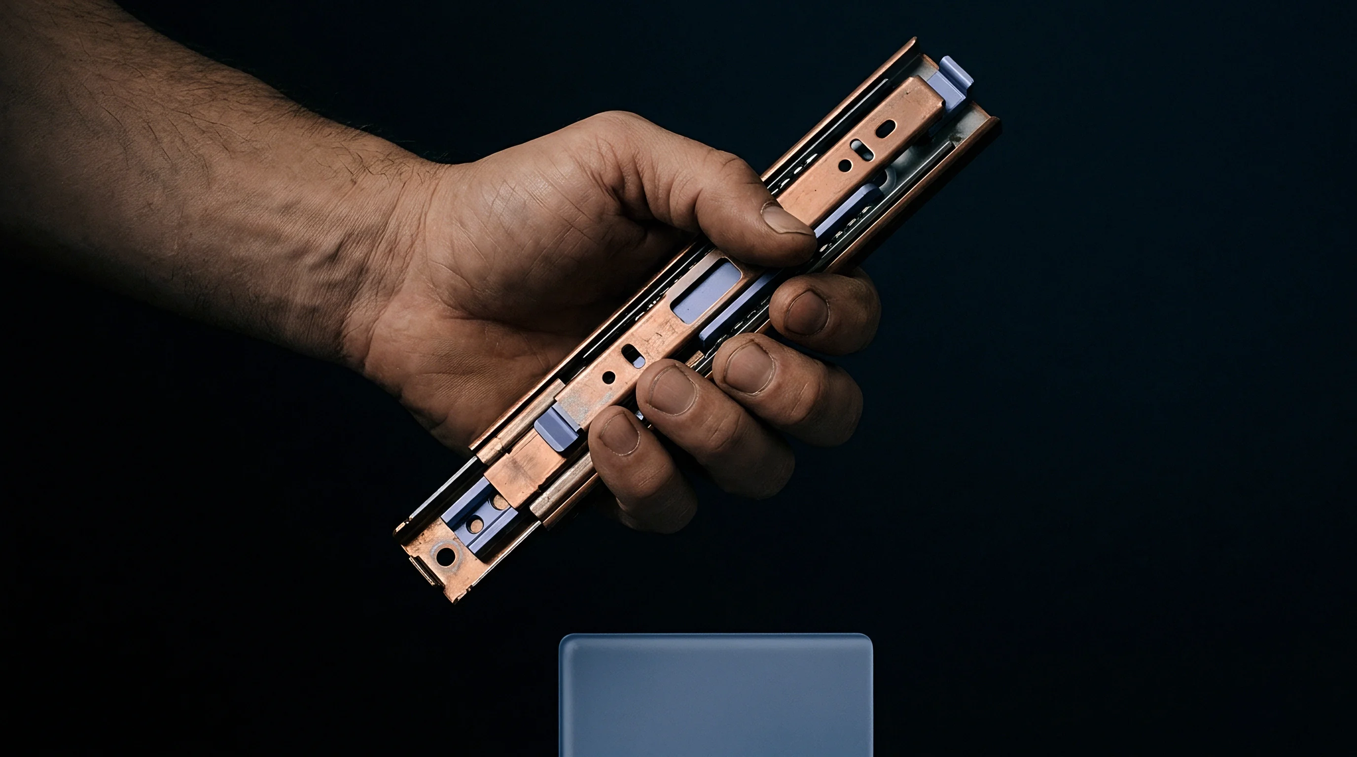
Femtosecond Pulse Micro Venting Geometries
Pulse durations under 10 picoseconds transfer energy faster than heat can diffuse into the tool steel. The material vaporizes almost instantly through cold ablation, producing clean micro-grooves with wall angles up to 82 degrees. Focused to a 15-micrometer spot, the laser carves micro-vent channels 10 to 30 micrometers deep and 20 to 50 micrometers wide along the roots of visual texture features.
These sub-surface channels intersect the primary aesthetic grain to form continuous exhaust routes toward parting lines or ejector pin clearances. Combining non-reflective matte texturing with functional gas pathways prevents air entrapment while maintaining a uniform surface appearance across the part.
Raster and Vector Channel Layout Strategy
Vector path strategies guide the laser along continuous calculated lines to cut deep collector channels, while raster patterns produce diffuse cross-hatched networks. Integrating vector micro-vents into rastered surface textures builds a hierarchical exhaust network inside the cavity. Primary micro-vents run parallel to the main melt flow direction, lowering resistance as gas is driven ahead of the polymer front.
Secondary transverse channels cross the primary paths at 45-degree angles, offering backup relief routes if converging melt fronts isolate individual texture cells. Channel depth tapers gradually from 30 micrometers at the center of the textured zone down to 10 micrometers near the flash threshold.
| Pulse Regime | Pulse Duration (ps) | Channel Depth (μm) | Channel Width (μm) | Exhaust Rate (cm³/s at 10 bar) | Recast Layer Thickness (μm) |
|---|---|---|---|---|---|
| Femtosecond | 0.8 | 15 ± 1.0 | 25 ± 1.5 | 4.2 | 0.0 |
| Femtosecond | 0.8 | 30 ± 1.2 | 45 ± 2.0 | 12.8 | 0.0 |
| Picosecond | 12.0 | 20 ± 2.0 | 30 ± 2.5 | 6.1 | 0.4 |
| Picosecond | 12.0 | 40 ± 2.8 | 60 ± 3.5 | 18.5 | 0.9 |
| Nanosecond | 50000.0 | 50 ± 5.0 | 80 ± 6.0 | 24.0 | 4.5 |
Surface Roughness and Depth Parameters
Sub-micron surface finish on the channel walls dictates boundary-layer friction during gas exhaust. Smooth channel floors produced by overlapping femtosecond laser passes at 90 percent hatch density lower pneumatic resistance by up to 35 percent compared to rougher nanosecond-ablated surfaces. Specifying surface roughness below Ra 0.4 micrometers inside venting grooves helps maintain high gas velocity.
- Load the three-dimensional CAD cavity surfaces and laser-texturing bitmap maps into the five-axis CAM programming environment.
- Extract the high-density melt-front convergence zones identified by mold filling simulation software.
- Superimpose the primary micro-vent vector network onto the aesthetic texture topography, aligning channels with natural grain valleys.
- Calculate laser power, repetition rate, and scan speed to yield 15-micrometer ablation steps without thermal melt accumulation.
- Execute five-axis laser ablation across the hardened steel mold insert using automated focal length compensation.
- Inspect channel geometry and depth using non-contact optical profilometry prior to mold assembly.
Laser texturing specifications must define depth tolerances within plus or minus two micrometers to maintain gas flow while preventing polymer flash.
Minor melt recast along channel ridges is often expected to wash away during initial mold break-in shots, though unremoved recast restricts gas flow.

Permeability
Pneumatic conductance defines how effectively micro-venting topography discharges air from a closed mold cavity during rapid injection. Resins enter the cavity under pressures from 300 to 1800 bar, displacing air that must escape without letting polymer leak into the exhaust channels. Balancing gas resistance against resin penetration requires matching vent land depth to the rheological behavior of the specific resin grade.

Which Channel Pitch Balances Gas Evacuation against Part Surface Flash?
Channel pitch determines how far air travels across a micro-textured feature before reaching an open exhaust line. A narrow pitch speeds gas evacuation but reduces steel contact area, altering local heat transfer and cooling uniformity. Spacing micro-vents between 0.5 and 1.5 millimeters apart maintains adequate exhaust capacity without compromising mold strength under high clamping forces.
Determining the ideal pitch depends on local wall thickness and injection speed. High-velocity filling requires tighter channel spacing to prevent backpressure ahead of the melt front.
| Polymer Family | Viscosity Class | MFR Range (g/10 min) | Max Non-Flashing Depth (μm) | Target Channel Width (μm) | Critical Shear Rate (1/s) |
|---|---|---|---|---|---|
| PA66-GF30 | Low Viscosity | 45 – 80 | 10 ± 1.5 | 30 ± 2.0 | 15,000 |
| PP (Unfilled) | Medium Viscosity | 12 – 25 | 18 ± 2.0 | 40 ± 3.0 | 10,000 |
| PC (Unfilled) | High Viscosity | 6 – 10 | 30 ± 2.5 | 60 ± 4.0 | 5,000 |
| PEEK (Glass Filled) | Extreme Temp | 3 – 8 | 12 ± 1.0 | 35 ± 2.5 | 20,000 |
| ABS (Standard) | Medium Viscosity | 15 – 30 | 22 ± 2.0 | 50 ± 3.5 | 8,000 |
Viscosity Limits and Vent Land Geometry
Polymer melt behavior inside micro-channels follows non-Newtonian power-law shear thinning. At elevated shear rates, melt viscosity drops sharply, increasing the risk that resin flashes into micro-vents cut too deep.
- Flash Threshold Penetration occurs when local cavity pressure overcomes resin shear resistance, forcing molten polymer into micro-channels deeper than the critical molecular slip boundary.
- Gas Lock Arrest happens when channel cross-sections are too narrow, causing backpressure that stops air evacuation and leaves unfilled part features.
- Parting Line Separation develops when unvented gas pressure forces mold halves apart slightly, creating heavy flash across primary parting surfaces.
- Micro-Venting Clogging results from condensation of low-molecular-weight additives and flame retardants inside micro-grooves operating below resin degradation temperatures.
Parting line micro-vent land lengths under 1.0 millimeter permit rapid gas exhaust but increase risk of steel wear under continuous clamp force cyclic loading.
Tooling purchase specifications typically stipulate that any laser micro-venting topography exceeding agreed flash depth limits must be corrected at the toolmaker’s expense ~ via re-welding and laser re-engraving ~ prior to final signoff.

Bench
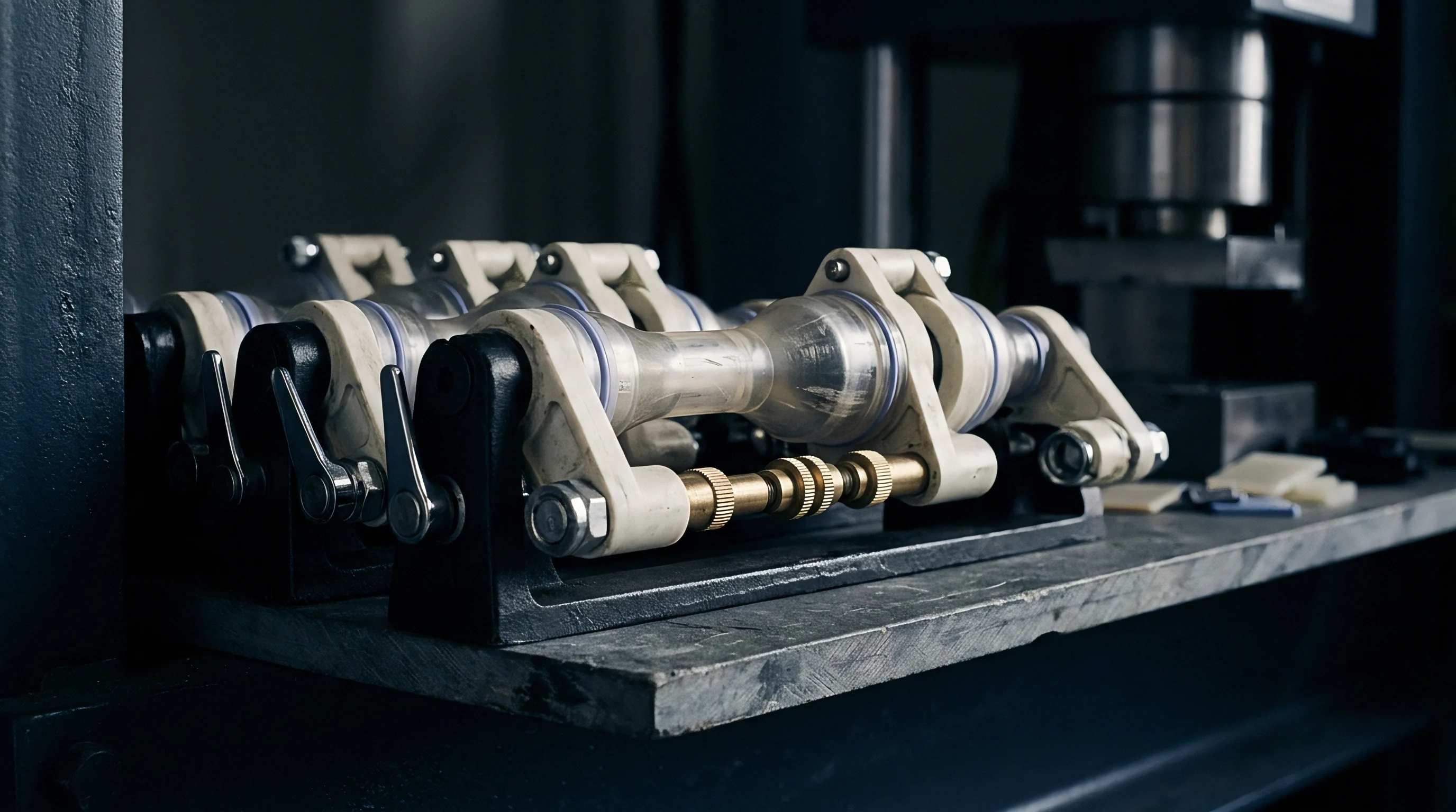
Evaluating micro-vent performance requires structured press-side testing during initial tool trials. Standard mold bring-up routines track air evacuation as the cavity fills from zero to 99 percent volume under decoupled scientific molding principles. Observing short shot progressions highlights where air pockets form, allowing engineers to refine injection velocity profiles or modify local vent topography before approving the tool for production.
Progressive short shots provide direct visual proof of how effectively micro-vents clear trapped air under actual filling conditions.

Short Shot Progression Studies
Injecting volumetric fills at 20, 40, 60, 80, and 95 percent part weight reveals the advancing melt front shape and gas entrapment behavior. Discoloration or micro-voids along weld lines highlight where air cannot escape freely. Recording the injection pressure needed to fill each step at a constant flow rate helps identify issues; a sudden pressure spike near the end of stroke indicates compressed gas rather than resistance from the polymer itself.
Adjusting injection velocity at specific screw positions shifts gas trap locations directly onto active laser micro-vents. When the vents perform properly, peak cavity pressure drops and parts fill cleanly without burn marks or flow hesitation.
Cavity Pressure Sensor Diagnostics
Piezoelectric pressure transducers placed behind laser-textured inserts monitor cavity pressure during filling and packing. Examining slope changes over the final 5 percent of fill reveals micro-vent effectiveness, where a smooth transition into packing pressure confirms unobstructed air displacement.
- Transducer Baseline Calibration establishes initial zero-pressure reference states before mold closure to ensure accurate reading of low-amplitude gas pressure spikes.
- Decoupled II Fill Isolation freezes screw position at 95 percent volume fill to evaluate passive gas venting without packing pressure assistance.
- Thermal Imaging Validation monitors ejection surface temperatures using infrared cameras to detect localized hot spots caused by micro-gas compression.
- Optical Micro-Inspection measures micro-channel cleanliness and wear after 5,000 continuous shots to determine cleaning interval frequency.
Cavity pressure traces exhibiting an abrupt secondary slope increase during filling indicate gas compression behind an advancing polymer front.
Micro-vent land depth is best verified using non-contact white-light interferometry, as mechanical dial indicators can easily damage delicate laser-engraved topographies.
Valuation
Adding micro-venting topography into laser texturing workflows changes the tooling cost structure compared to conventional mechanical vent grinding or EDM slotting. While five-axis laser equipment carries higher machine-hour rates, it eliminates manual benching and custom electrode fabrication. Weighing total tooling economics involves balancing higher laser quotes against scrap reduction and longer maintenance cycles over high-volume production runs.

Tooling Capex and Laser Processing Overhead
Laser texturing quotes reflect digital model preparation, machine setup, and actual laser-on raster time. Adding functional micro-vents to an aesthetic grain program increases digital prep time by about 15 to 25 percent. Machine time increases by 10 to 18 percent to run the extra vector passes required for deep collector channels.
On a complex two-cavity automotive interior trim mold, laser texturing with integrated micro-vents adds $4,500 to $8,200 to initial tool construction. Eliminating manual secondary venting and cutting down on T1 trial iterations partially offsets that upfront cost.

Maintenance Cycles and Inserts Refurbishment Arithmetic
Production tools with micro-vent topographies build up outgassing residue inside fine channels over time, requiring periodic cleaning to clear vaporized polymer deposits before full refurbishment is needed to restore the original channel geometry. Steel selection also influences laser absorption during tool touch-ups. Standard ultrasonic bath cleaning in a mild solvent clears these deposits without eroding delicate ablated channel edges.
A mid-volume tool running 30 percent glass-filled polyamide requires micro-vent cleaning roughly every 40,000 shots to prevent channel constriction. Over a one-million-part production life, scheduled micro-vent cleaning costs about $12,000 ~ compared to an estimated $45,000 in scrap, burn repairs, and manual sorting incurred by unvented tooling.
What long-term degradation mechanisms alter femtosecond laser micro-vent discharge efficiency when molding aggressive fluoropolymer or flame-retardant compounds over two million cycles?