Cavity Topography Impact on Microscopic Thermal Resistance in Molds
Cavity surface roughness traps micro-voids that raise interfacial thermal resistance, requiring higher packing pressure or finer polishing to prevent cycle drag.

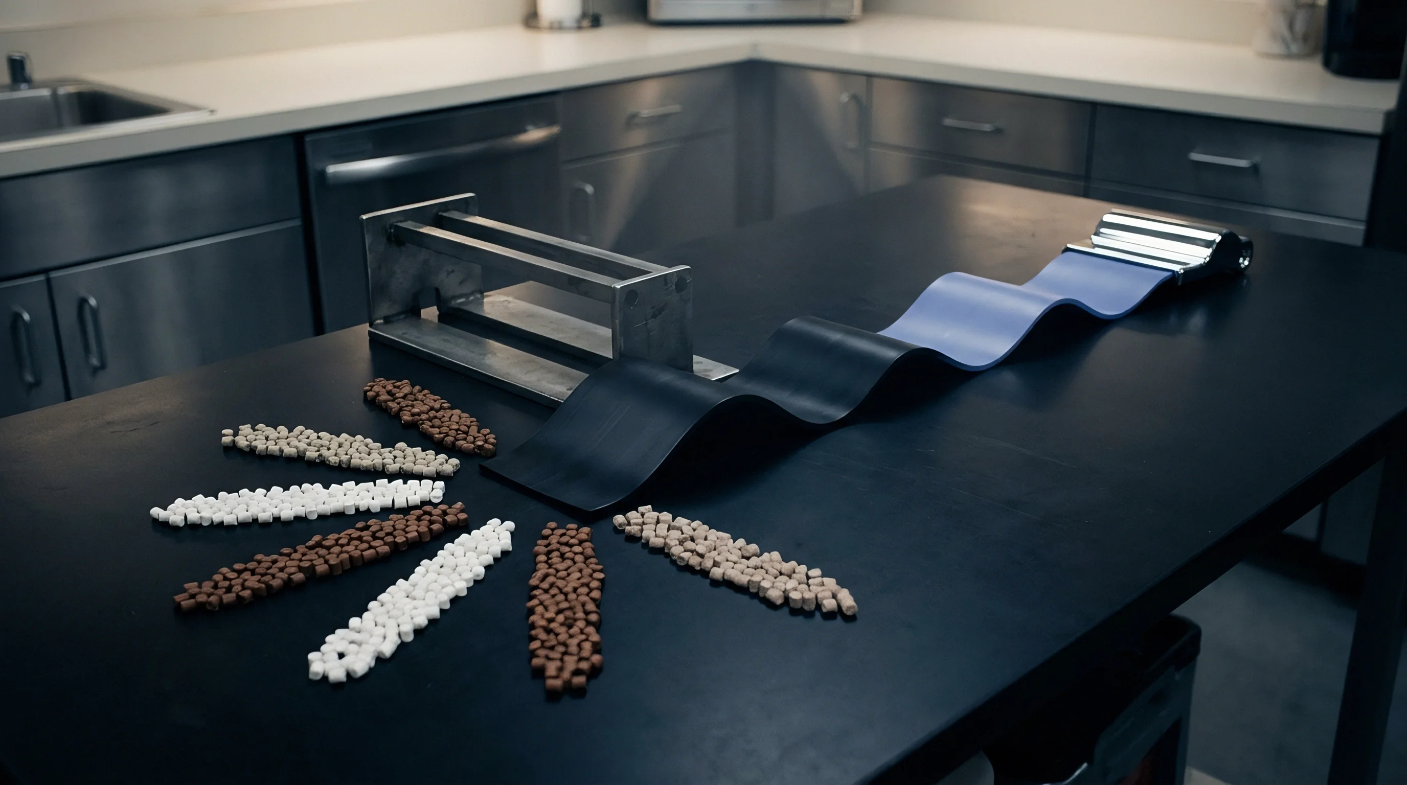
Asperity
Cavity surface micro-geometry governs the interfacial heat transfer coefficient between molten polymer and tool steel during the earliest milliseconds of injection. When molten resin meets the cavity wall, microscopic peak-to-valley deviations prevent uniform contact across the nominal surface area. Microscopic surface peaks arrest the advancing melt front while microscopic valleys trap microscopic pockets of air and volatilized processing aids.
The resulting microscopic air gaps introduce a localized thermal barrier. Heat flux drops across the boundary layer.
Tool designers often treat thermal dissipation as a bulk conduction problem governed solely by steel conductivity and coolant channel proximity. Physical trials show interfacial contact resistance accounts for up to thirty percent of total thermal resistance during initial skin formation. The microscopic boundary layer sets the cooling rate before the solidifying shell thickens enough for internal conduction to dominate.
This boundary layer determines frozen layer thickness, skin morphology, and the initial replication of cavity finish.
Polishing cavity steel from Ra 0.40 micrometers down to Ra 0.05 micrometers drops the initial interfacial thermal resistance by half under four hundred bar holding pressure.
Microscopic interfacial thermal resistance, designated as Rth, acts inversely to the contact heat transfer coefficient, h. At initial polymer-metal contact, h ranges between 500 and 2,500 W/(m²·K) on rough textured surfaces, whereas mirror-polished cavities yield values exceeding 5,000 W/(m²·K). The disparity stems from true contact area ratios.
Microscopic surface roughness parameters dictate how deeply molten polymer penetrates the valleys under hydraulic packing pressure. Ra describes average roughness, yet Rz and the mean peak spacing RSm govern interfacial heat transport more aggressively by defining microscopic void volume.
When the polymer touches microscopic metal peaks, those contact points conduct heat through direct solid-to-solid contact. The air pockets trapped inside adjacent microscopic troughs possess a thermal conductivity below 0.03 W/(m·K), while tool steel conducts between 20 and 45 W/(m·K). Heat flows selectively through the microscopic contact summits.
This constriction of heat flow lines into isolated asperity junctions generates microscopic thermal contact resistance. Higher surface roughness decreases real contact area, constricting heat lines and slowing early melt solidification.
Tooling drawings that omit specific micro-topography parameters leave the interfacial heat transfer coefficient unanchored, shifting cycle times beyond quoted thermal margins.


Contact
Interfacial thermal resistance evolves dynamically across the moulding cycle. During the filling phase, dynamic melt pressure drives the viscoelastic polymer melt into microscopic surface crevices. The polymer skin freezes instantaneously upon meeting the cold cavity steel.
If injection speed or cavity pressure remains low during initial filling, the frozen skin bridges across microscopic asperity peaks, leaving trapped air beneath. High holding pressure forces the warm core against the skin, pushing the polymer into microscopic surface features and collapsing interfacial micro-voids.
Holding pressure collapses trapped micro-voids and thins the interfacial thermal barrier. Dynamic contact resistance drops to its cycle minimum during the early packing phase. The real contact area expands toward seventy to eighty percent of the nominal cavity surface area.
Direct polymer-to-metal conduction increases accordingly. Interfacial heat flux peaks, transferring heat rapidly into the tool steel and accelerating solid skin growth.
Cooling induces volumetric shrinkage within the bulk polymer. As the core freezes and changes specific volume, the solidified shell contracts away from the cavity wall. Interfacial pressure drops steadily toward zero bar.
Microscopic contact summits detach from the steel wall, reintroducing microscopic air voids. Thermal resistance climbs sharply once contact pressure drops below fifty bar. In unsupported part areas such as deep box walls or flat aesthetic covers, complete microscopic detachment occurs, leaving an air gap of five to twenty micrometers.
Interfacial heat transfer coefficient collapses below 200 W/(m²·K).

Dynamic Interfacial Heat Transfer Regimes
The transition between contact regimes dictates local heat rejection rates throughout injection, packing, and cooling phases.
| Cycle Phase | Contact State | Typical Contact Pressure (bar) | Interfacial h (W/(m²·K)) | Interfacial Rth ((m²·K)/W) |
|---|---|---|---|---|
| Initial Filling | Dynamic spreading over microscopic summits | 50 to 150 | 800 to 1,500 | 0.00067 to 0.00125 |
| Peak Packing | High conformation into microscopic valleys | 300 to 800 | 3,500 to 6,000 | 0.00017 to 0.00028 |
| Late Holding | Early volumetric contraction, partial asperity contact | 100 to 250 | 1,800 to 2,800 | 0.00036 to 0.00055 |
| Cooling Phase | Microscopic detachment, gap formation | 0 to 20 | 150 to 350 | 0.00285 to 0.00667 |
| Values representative of semi-crystalline polypropylene processed in 1.2343 tool steel at 40 degrees Celsius mould temperature under standard ISO 294 conditions. | ||||
The data demonstrates that thermal resistance is non-static. Settling on an average thermal transfer coefficient across the cooling cycle obscures the critical window where skin freeze occurs. Processors operating high-speed tools observe that slight deviations in packing pressure translate into significant cooling time extensions because incomplete valley penetration prolongs the high-resistance phase.
Tool steel surfaces with uniform micro-textures sustain stable contact resistance across multiple shots. Electro-discharge machining surfaces exhibit spherical micro-craters with rounded rims. Milled surfaces display oriented feed ridges with sharp peaks.
Under equal hydraulic clamp force, the sharp ridges on a milled surface experience higher localized contact pressure, yielding greater local polymer penetration than rounded EDM craters of identical average roughness Ra. Microscopic contact area develops differently depending on the machining method selected to finish the steel.
Failure to hold packing pressure above the threshold required to seat resin against asperity peaks extends required cooling durations and increases thermal variation across the moulding.
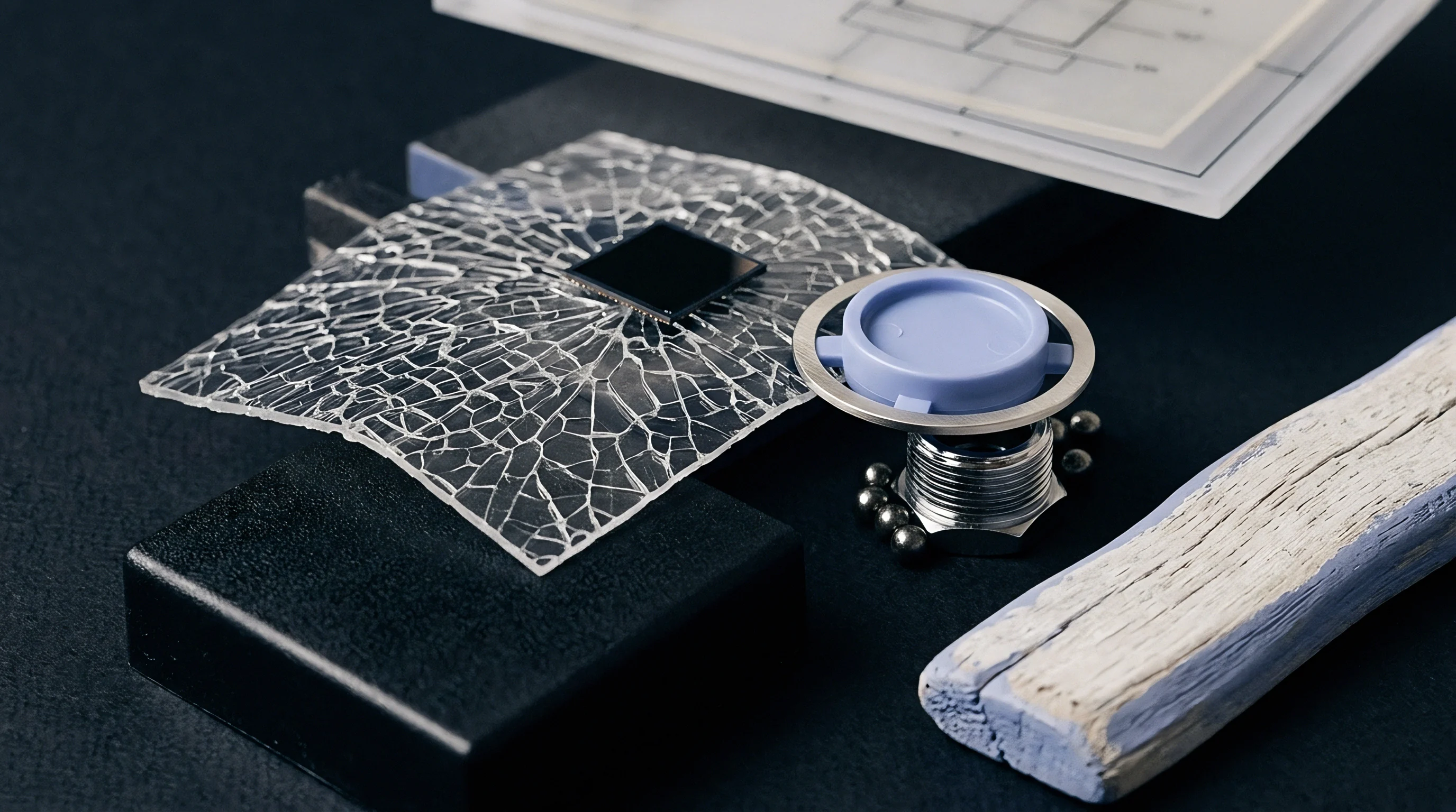

Texture
Tool specifications frequently designate surface finishes through standardized scales such as VDI 3400 or Mold-Tech standards. These designations dictate visual gloss and demoulding draft angles. They simultaneously dictate the baseline interfacial thermal resistance of the mould cavity.
An acid-etched texture introduces complex multi-scale roughness. Primary plateaus support secondary micro-cavities that entrap gas during rapid cavity filling.
Higher roughness numbers systematically lower thermal extraction rates. When running semi-crystalline polymers like polyamides or polyoxymethylene, slower heat extraction through textured cavity faces retards crystallization rates in the surface layer. The skin layer cools slowly, allowing spherulites to grow larger.
A polished core side pulls heat faster than a textured cavity side. This asymmetric heat flux creates an unbalanced internal stress profile across the nominal part wall thickness, inducing post-mould warpage.
A difference of two micrometers in surface roughness between cavity and core halves creates thermal imbalances sufficient to warp flat panels out of drawing tolerance.
The processing window narrows as texture depth increases. To replicate heavy textures, setters must maintain higher melt temperatures and prolong injection velocity profiles. The higher temperature delays initial skin solidification, permitting the polymer to replicate cavity topography.
The consequence is an increased cumulative thermal load on the mould steel, requiring longer cycle times to pull sufficient heat out of the core before ejection.

Topography Metrics across Tooling Surface Finishes
Tool finishes vary widely in their micro-topographical descriptors, altering interfacial heat flow dynamics.
| Surface Finish Grade | Machining Process | Roughness Ra (micrometers) | Mean Spacing RSm (micrometers) | Effective Thermal Resistance ((m²·K)/W) |
|---|---|---|---|---|
| SPI A-1 | Diamond Polish 3 micron | 0.012 to 0.025 | 10 to 18 | 0.00015 to 0.00022 |
| SPI B-1 | 600 Grit Paper | 0.050 to 0.100 | 25 to 45 | 0.00028 to 0.00038 |
| VDI 18 | Fine EDM | 0.800 | 65 to 90 | 0.00065 to 0.00085 |
| VDI 27 | Medium EDM | 2.240 | 120 to 160 | 0.00110 to 0.00145 |
| MT-11010 | Chemical Etch | 3.500 to 4.200 | 180 to 240 | 0.00160 to 0.00210 |
Specifying a heavy grain on an aesthetic housing commits the production cell to lower thermal throughput. Tool builders who compensate by adding water lines often discover that bulk steel cooling cannot overcome interfacial thermal choke points. The thermal choke resides entirely at the polymer-metal boundary.
The low thermal conductivity of trapped micro-void gases limits conduction into the tool.
Mould builders typically state that textured surfaces increase release friction rather than affecting cycle time, framing extended cooling cycles entirely as a mechanical ejection requirement.

Air
Microscopic gas pockets trapped between tool steel and molten polymer act as localized thermal insulation layers. Cavity air consists of atmospheric gases alongside volatile organic compounds, moisture, and vaporized additives outgassing from the melt front. When the injection screw drives melt into the tool, displaced air escapes through parting line vents, ejector pin clearances, and porous steel inserts.
At the microscopic level, air residing inside cavity asperities cannot escape through macro-vents.
Trapped microscopic gas becomes compressed as melt advances under injection pressure. Microscopic pockets reach pressures upwards of fifty bar depending on local pack pressure transmission. While gas compression raises gas density and marginally increases thermal conductivity, thermal conductivity remains two orders of magnitude lower than that of the surrounding steel.
Conduction across these compressed micro-voids remains negligible. Radiation heat transfer across five-micrometer voids contributes under one percent of total heat flux at typical moulding temperatures between 180 and 280 degrees Celsius.
- Entrapment occurs when the advancing melt front bridges across microscopic peaks without wetting the recessed troughs of the steel.
- Compression takes place as hydraulic packing forces the molten core against the skin, pressurizing trapped pocket gases into smaller volumes.
- Decompression begins when cavity pressure drops below peak levels, allowing trapped pocket gases to expand slightly as the polymer shell solidifies.
- Isolation finalizes as bulk polymer shrinkage pulls the rigid skin clear of the steel peaks, combining individual micro-voids into a continuous macroscopic insulating air gap.
Trapped gas composition shifts during extended production shifts. Decomposing polymer processing aids deposit low-conductivity organic films inside microscopic tool valleys. This fouling layer, known as mould deposit, progressively fills cavity micro-crevices.
The deposit exhibits thermal conductivity near 0.15 W/(m·K), permanently degrading local contact heat transfer even when dynamic holding pressure remains within specification limits.
Mould maintenance schedules that rely exclusively on visual inspection miss thin microscopic deposits that alter heat transfer profiles without visibly degrading surface gloss.

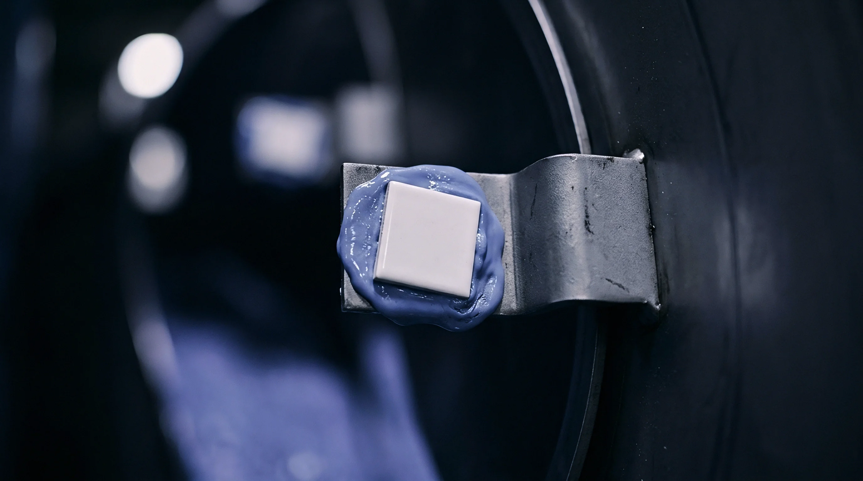
Rheology
Viscoelastic flow behavior dictates how thoroughly a polymer melt conforms to cavity micro-topography. Melt viscosity varies inversely with shear rate and melt temperature. High-shear injection drives lower-viscosity melt deeply into micro-asperity valleys, reducing microscopic void volume.
Low-viscosity grades achieve intimate contact with cavity steel rapidly, yielding high interfacial heat transfer coefficients during early filling.
Polymer morphology further dictates contact resistance dynamics. Semi-crystalline resins like high-density polyethylene, polypropylene, and polybutylene terephthalate exhibit volumetric shrinkage between 1.5 and 2.5 percent. Amorphous resins like polycarbonate, acrylonitrile butadiene styrene, and polymethyl methacrylate shrink between 0.4 and 0.7 percent.
The severe volumetric shrinkage of semi-crystalline materials initiates micro-gap formation early in the cooling cycle. Amorphous resins sustain physical contact with tool steel asperities longer, maintaining lower interfacial thermal resistance throughout cooling.
Under standard processing conditions, semi-crystalline resins experience contact detachment twenty to forty percent earlier in the cooling cycle than amorphous polymers of identical wall thickness.
Glass fibers and mineral fillers alter contact mechanics substantially. Filled resins exhibit higher bulk thermal conductivity than unfilled base polymers. Highly filled compounds increase interfacial contact resistance by preventing complete microscopic conformation.
Rigid glass fibers protruding through the melt surface bridge microscopic valleys on the cavity steel, holding the polymer matrix away from the metal. The true contact area drops, increasing microscopic thermal resistance despite the higher thermal conductivity of the glass inclusions.

Polymer Melt Properties Influencing Interfacial Heat Transfer
- Apparent Viscosity controls how easily the melt flows into microscopic tool crevices under transient shear stresses during filling.
- Crystallization Rate determines the speed of volumetric shrinkage, which accelerates microscopic detachment from tool steel asperities.
- Filler Loading introduces rigid particles that bridge microscopic tool valleys and lower the real contact area of the polymer matrix.
- Thermal Diffusivity governs the rate at which heat transfers through the bulk resin once heat clears the interfacial contact boundary.
Processing parameters directly modify these material interactions. Increasing tool temperature softens the advancing polymer shell, improving microscopic replication and reducing thermal resistance. Increasing mould temperature simultaneously reduces the temperature difference driving heat transfer.
The net impact on cooling cycle time depends on the balance between reduced interfacial thermal resistance and the lower overall temperature gradient.
The unresolved challenge is isolating whether microscopic replication improves primarily from lowered melt viscosity or delayed skin freeze when tool temperatures approach the glass transition point.
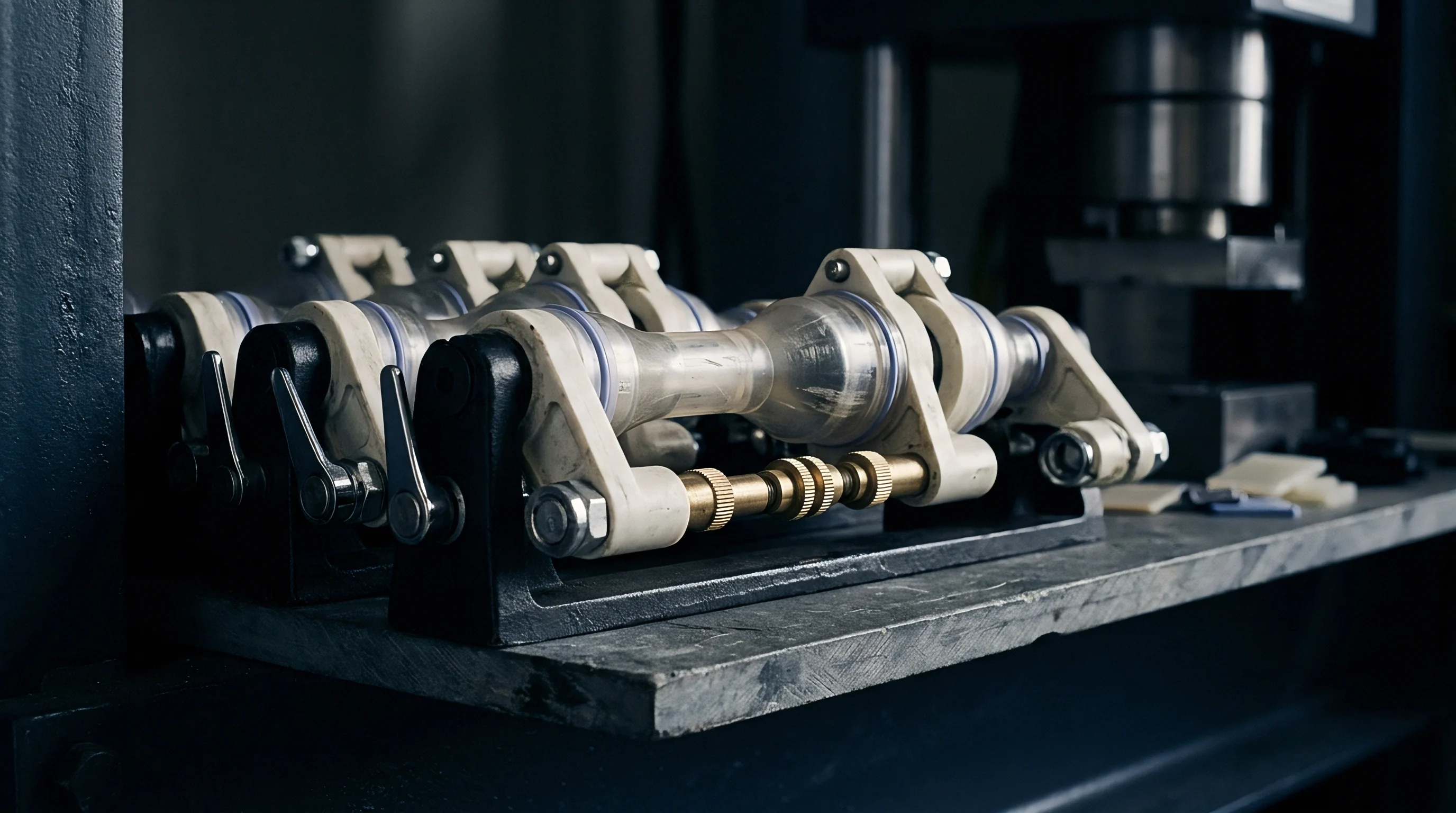
Stress
Localized variations in interfacial thermal resistance induce non-uniform cooling rates that generate residual stresses. When cavity topography varies across a single moulding, regions with high thermal resistance cool slower than polished regions. Slower-cooling regions experience extended molecular relaxation, higher local crystallinity, and greater volumetric shrinkage.
Rapidly cooling regions develop thin, highly oriented skin layers with frozen-in orientation stresses.
Differential shrinkage between adjacent areas on a part drives out-of-plane distortion. A common design layout involves textured external aesthetic surfaces backed by polished internal ribs and core surfaces. The core steel pulls heat out rapidly, establishing a steep thermal gradient toward the inside of the part.
The textured external surface transfers heat slowly due to high interfacial thermal resistance. The polymer freezes asymmetrically from the inside out, bending the component toward the faster-cooling core side.
Residual thermal stresses accumulate until the part is ejected from the mould. Upon release from mechanical tool constraints, residual stress balances out through instantaneous elastic warpage and long-term creep deformation. Parts held within tight tolerance bands on the tool drawing fail quality inspection when thermal resistance discrepancies warp features beyond DIN 16742 tolerance grades.
The magnitude of residual stress correlates with the cooling rate delta between opposite part surfaces. A cooling rate difference of fifteen degrees Celsius per second across a two-millimeter wall thickness introduces bending moments sufficient to cause measurable distortion in unfilled polypropylene components. Post-mould annealing reduces peak internal stresses, yet secondary heating processes introduce dimensional shrinkage that shifts final part geometry out of drawing limits.
Tooling drawings that balance cavity texture against equivalent core finishes minimize thermal gradients, eliminating the underlying driver of asymmetric cooling warpage.

Expense
Microscopic thermal contact resistance directly impacts production economics by dictating required cooling time. Cooling time comprises sixty to seventy percent of the total injection moulding cycle. Extending cooling time to compensate for high interfacial thermal resistance inflates the machine-hour cost allocated to each produced part.
High-cavitation tooling magnifies cycle time extensions into substantial financial penalties over multi-million-part production contracts.
A typical scenario clarifies the economic exposure. Consider a thirty-two cavity tool running an automotive interior trim clip in unfilled polyoxymethylene on a 150-tonne injection press with a shop-floor machine rate of seventy dollars per hour. The component features a 1.8-millimeter wall thickness.
The initial tool specification calls for a VDI 30 spark-eroded finish across the entire cavity to hide witness lines, while the core features an SPI B-2 polished finish.
Due to the high interfacial thermal resistance of the VDI 30 finish, heat removal through the cavity lags behind the core. The press setter extends cooling time by 2.8 seconds per cycle to eliminate warpage upon ejection and allow the thicker wall sections to solidify below the HDT threshold of 110 degrees Celsius. Across an annual volume of five million parts, the cost impact develops rapidly.
- The baseline cycle time of 11.2 seconds yields 321 shots per hour, delivering 10,272 parts per operating hour.
- The extended cycle time of 14.0 seconds drops output to 257 shots per hour, delivering 8,224 parts per operating hour.
- Producing five million parts at 11.2 seconds requires 486.8 press hours, costing $34,076 in machine time.
- Producing five million parts at 14.0 seconds requires 608.0 press hours, costing $42,560 in machine time.
The cycle extension consumes $8,484 in additional machine-hour allocation annually on a single tool. Across a five-year production contract, this thermal contact penalty totals $42,420. Polishing the tool steel from VDI 30 down to VDI 18 or applying a uniform fine EDM texture requires a one-time tooling modification fee of $3,200.
The tool modification cost amortizes within the first five months of series production through recovered cycle efficiency.
Tool procurement contracts that specify maximum allowable cooling times per millimeter of wall thickness protect the buyer from absorbing machine-hour inflation caused by unverified cavity finishes.