Piezoelectric Cavity Pressure Sensor Installation and Calibration Procedures
Machining sensor bores to strict concentricity tolerances and establishing direct picoCoulomb calibration scales cavity pressure for closed-loop process control.
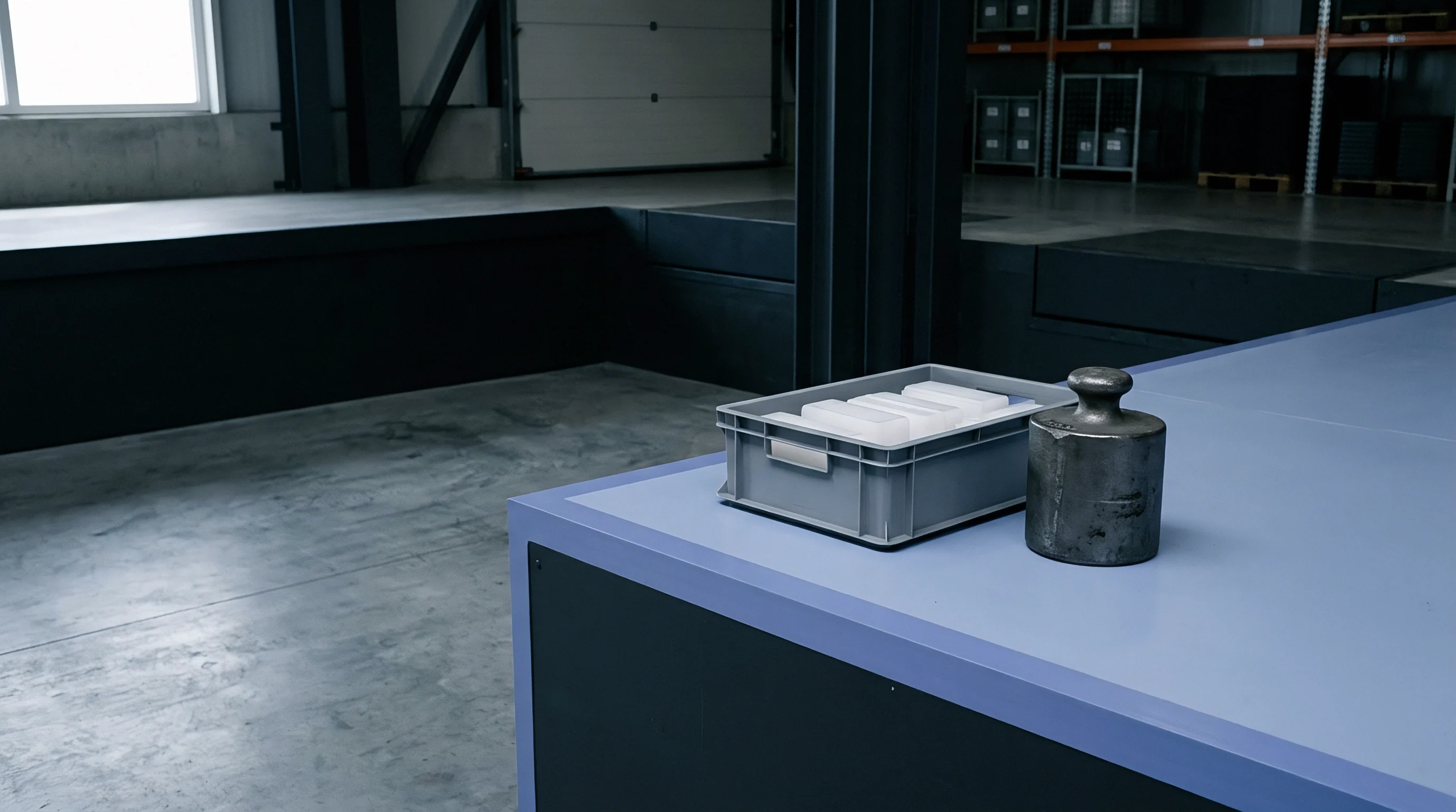

Bore
Direct piezoelectric cavity pressure sensors demand precise pocket machining in hardened tool steel to prevent sensor diaphragm damage and signal distortion. The front face of a direct quartz sensor acts as an active portion of the cavity wall. Any misalignment between the sensor face and the surrounding steel creates part defects or mechanical failure.
A sensor seated proud of the cavity surface flashes steel edges against the opposing tool half, while a recessed sensor creates a witness mark and risks plastic melt freezing over the sensing diaphragm.
Machining geometry dictates the mechanical stability of the transducer under high cyclic injection loads. Sensor bores require tight dimensional control on concentricity, bore diameter, bottom seating flatness, and perpendicularity relative to the parting line. Toolrooms execute these features on precision sinker electrical discharge machining or jig grinding equipment after heat treatment to avoid distortion during hardening cycles.
| Sensor Mounting Parameter | Direct Diaphragm Transducer | Indirect Under-Pin Transducer | Critical Tooling Tolerance |
|---|---|---|---|
| Bore Diameter Tolerance | +0.012 mm / -0.000 mm | +0.020 mm / -0.000 mm | H7 reamed or wire-cut bore |
| Seating Surface Flatness | 0.005 mm total indicator runout | 0.008 mm total indicator runout | Lapped or spark-eroded seat |
| Perpendicularity to Cavity Face | 0.010 mm per 50 mm depth | 0.015 mm per 50 mm depth | Square to cavity waterline |
| Seating Surface Roughness | Ra 0.4 micrometers | Ra 0.8 micrometers | Micro-milled or ground finish |
| Diaphragm Flushness Target | -0.005 mm to -0.015 mm recessed | Not exposed to cavity melt | Measured cold via depth micrometer |
Thermal expansion differences between the transducer body and the mold insert shift the relative height during steady-state processing. Toolmakers set the sensor diaphragm cold recess to 0.010 millimeters for semi-crystalline resins running at elevated mold temperatures. The thermal expansion of the steel insert closes this gap at operating temperature.
A direct sensor sitting exactly flush at room temperature expands proud by 0.008 millimeters when the tool reaches 140 degrees Celsius.
The DIN 16742 TG4 tolerance class mandates rigid pocket concentricity to isolate piezoelectric quartz elements from bending moments.
Tool steel selection around the sensor pocket governs long-term seat integrity. Grades such as 1.2343 ESR or 1.2083 quenched to 52 HRC resist compressive indentation from the sensor housing under 2000 bar cavity pressure peaks. Soft P20 pre-hardened steels yield beneath the sensor base after several hundred thousand cycles, causing progressive signal loss and zero-point drift.
A supplier often claims standard milling delivers adequate sensor pocket concentricity without post-heat-treat grinding.

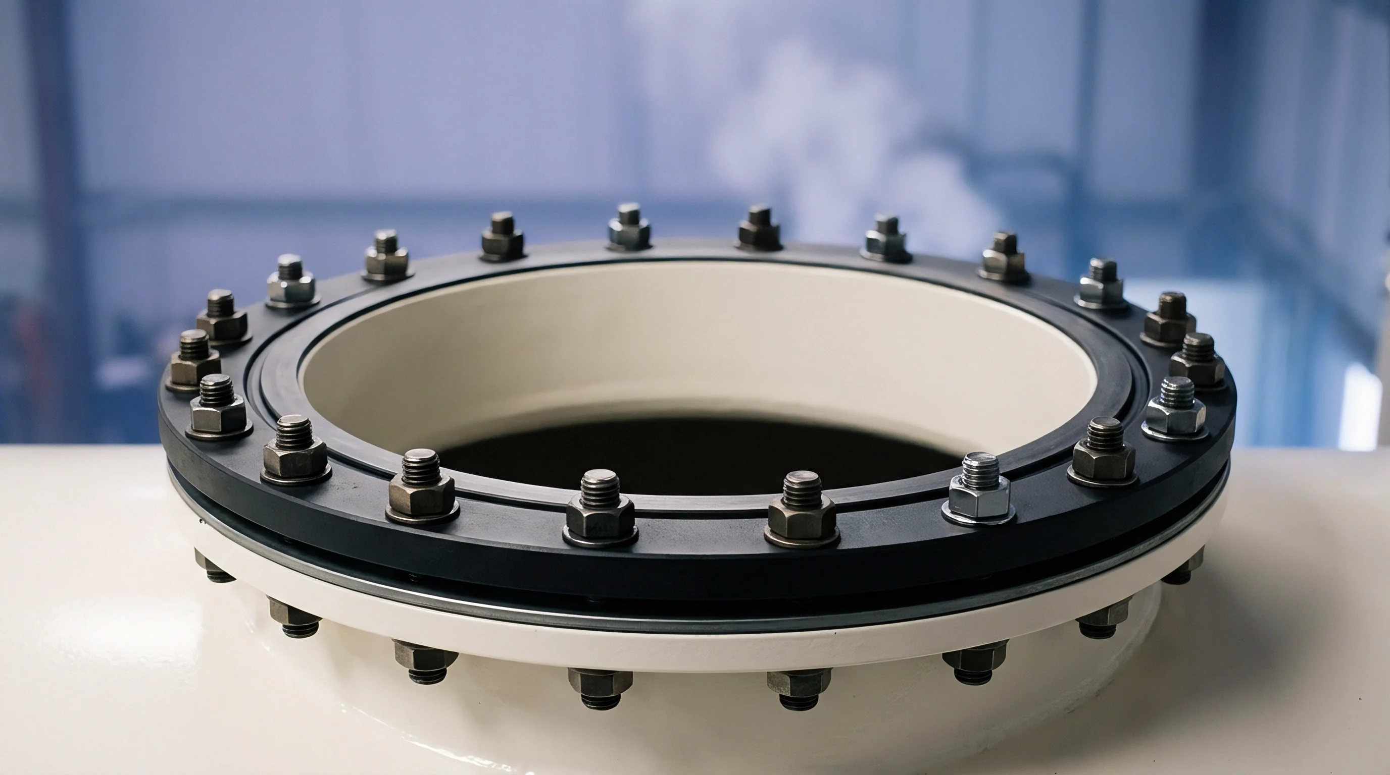
Pin
Indirect cavity pressure measurement relies on a standard ejector pin or dummy load pin to transfer melt pressure from the cavity to a load washer mounted behind the pin plate. Force transmission follows basic mechanics where cavity pressure acts across the pin cross-sectional area. The transducer records total force in Newtons, which the setter converts to pressure in bar using the measured face diameter of the pin.

Why Do Indirect Load Pins Attenuate Dynamic Signals?
Mechanical friction between the ejector pin shank and the insert bore introduces hysteresis into the pressure curve. As injection pressure builds, the pin expands slightly under axial load while sliding forward, generating frictional drag against the tool steel. This friction delays the recorded pressure onset during filling and artificially elevates the indicated residual pressure during cooling.
- Clearance gap dimensioning limits polymer melt ingress while maintaining free axial travel under thermal expansion.
- Pin length minimization prevents column buckling and side-load transmission to the quartz washer.
- Preload spacer grinding eliminates free play between the pin head, sensor face, and backing plate.
- Hardened guide bushings preserve axial alignment and prevent pin galling across automated cycling.
Preload on indirect sensors maintains continuous mechanical contact between the ejector pin head and the transducer face during the entire cycle. Without adequate preload, the pin strikes the quartz face dynamically at fill onset, causing signal ringing and false peak readings. Tool builders set preloads between 10 percent and 20 percent of the sensor measuring range using precision ground shims.
Indirect load pin setups lose between five and twelve percent of actual cavity pressure to pin-bore frictional drag under standard clearance fits.
The diameter of the transmission pin governs signal resolution. Small pin diameters concentrate force on a compact surface, risking local plastic deformation on soft backing plates. Large pins capture higher absolute force, improving signal-to-noise ratio in low-pressure processes such as structural foam or thin-wall packaging.
Neglecting pin alignment checks creates severe side-loading on quartz elements, fracturing internal crystals on high-speed injection strokes.

Cable
Piezoelectric quartz transducers operate in the electrostatic charge regime, generating tiny electric charges measured in picoCoulombs. A pressure swing of 1000 bar produces a total charge output of roughly 2000 to 5000 picoCoulombs depending on sensor sensitivity. Preserving this charge requires ultra-high insulation resistance across every cable, connector, and terminal block in the wiring harness.
Cable routing within the mold base demands dedicated channels isolated from water lines, hydraulic circuits, and mechanical moving plates. Crushing a high-impedance cable destroys its shielding, while exposure to cooling water or hydraulic oil degrades insulation resistance from terraohms down to megaohms. Contaminated connectors cause immediate charge leakage, visible as severe negative drift on the press monitor trace.
| Harness Attribute | Minimum Specification | Operational Threshold | Failure Indicator |
|---|---|---|---|
| Insulation Resistance | 100 Terraohms (10^14 Ohm) | 10 Terraohms (10^13 Ohm) | Downward baseline signal decay |
| Bending Radius Limit | 5x cable outer diameter | 8x cable outer diameter | Internal core conductor shear |
| Continuous Temperature Rating | 200 degrees Celsius | 160 degrees Celsius | PTFE dielectric melting |
| Connector Tightening Torque | 1.2 Newton-meters | 0.8 to 1.4 Newton-meters | Intermittent signal dropouts |
| Triboelectric Protection | Conductive graphite layer | Shield ground continuity | Spurious motion-induced spikes |
Specialized low-noise coaxial cables feature a graphite coating between the dielectric insulator and outer braided shield. This layer dissipates static charges generated by cable flexure during tool movement. Standard industrial coaxial cables lack this coating and generate false pressure spikes of 50 to 200 bar from mechanical vibration alone.
Insulation resistance below ten terraohms dissipates sensor charge into ground before the amplifier records peak cavity pressure.
Technicians verify cable integrity using specialized high-voltage insulation testers operating at 50 to 100 volts direct current. Standard multimeters use low test voltages unable to detect micro-cracks in fluoropolymer insulation or sub-microscopic moisture films inside Fischer or BNC connectors.
A setter cleans contaminated connectors with residue-free isopropanol, drying them with clean oil-free nitrogen before reassembly.

Scale
Charge amplifiers convert raw picoCoulombs from quartz crystals into calibrated proportional voltages, typically 0 to 10 volts direct current. The calibration factor, expressed as picoCoulombs per bar for direct sensors or picoCoulombs per Newton for indirect load washers, originates from manufacturer factory calibration certificates traceable to national metrology standards.

Where Do Thermal Offsets Distort Peak Pressure Values?
Rapid temperature rises at the sensor diaphragm during cavity filling generate transient thermoelectric charges. Pyroelectric effects alter the baseline voltage before melt pressure fully registers against the mechanical quartz structure. Modern quartz elements utilize specific crystal cuts, such as transverse effect cuts, to decouple thermal expansion stresses from piezoelectric charge generation.
- Mount the sensor in a dedicated hydraulic calibration bench equipped with a certified reference master load cell.
- Apply three progressive preload cycles up to the maximum operating pressure of 2000 bar to seat mechanical interfaces.
- Execute a five-point stepped pressure ladder, recording generated charge output at zero, 500, 1000, 1500, and 2000 bar.
- Calculate the linear regression slope to verify sensitivity match within 0.5 percent of the manufacturer calibration sheet.
- Program the calculated sensitivity scale factor directly into the press controller or standalone charge amplifier.
The mathematical conversion for direct sensors follows basic multiplication of sensor sensitivity by target pressure range. For indirect sensors, the equation incorporates pin surface area:
Pressure equals the measured force divided by the pin frontal area. A sensor with a sensitivity of 4.2 picoCoulombs per Newton mounted beneath a 3.0 millimeter ejector pin yields an effective sensitivity of 29.69 picoCoulombs per bar. An error of 0.05 millimeters in measured pin diameter introduces a 3.3 percent systematic scaling error across the entire pressure range.
| Pin Diameter | Frontal Area | Transducer Sensitivity | Combined Sensitivity Scale |
|---|---|---|---|
| 2.0 mm | 3.14 sq mm | 4.00 pC / N | 12.57 pC / bar |
| 3.0 mm | 7.07 sq mm | 4.00 pC / N | 28.27 pC / bar |
| 4.0 mm | 12.57 sq mm | 4.00 pC / N | 50.27 pC / bar |
| 5.0 mm | 19.63 sq mm | 4.00 pC / N | 78.54 pC / bar |
| 6.0 mm | 28.27 sq mm | 4.00 pC / N | 113.10 pC / bar |
Charge amplifier reset timing defines signal stability. Switching the amplifier from reset to measure mode immediately prior to screw forward movement eliminates long-term electrostatic drift. Holding an amplifier in measure mode across long cooling phases invites environmental noise integration.
Dynamic calibration shifts over extended production runs remain subject to ongoing industry debate regarding in-situ tool recertification intervals.

Envelope
Process monitoring relies on the cavity pressure profile as the definitive record of polymer behavior inside the mold. Machine hydraulic pressure reflects screw behavior, while cavity pressure reflects what the plastic melt actually experiences during fill, pack, and hold. Real-time cavity pressure monitoring detects viscosity shifts, short shots, sink marks, flash, and gate freeze variations instantly.
Switchover from velocity-controlled filling to pressure-controlled packing executed via cavity pressure eliminates part weight variance. As melt reaches the sensor position near the end of fill, the rapid pressure rise triggers the machine controller to transfer injection stages. This decoupled control method isolates part density from batch-to-batch resin viscosity swings and regrind percentage shifts.
Quality envelopes establish upper and lower boundary limits around four key metrics extracted from the cycle curve. Parts falling outside these dynamic limits trigger automated reject gates downstream of part ejection.
- Integral cavity pressure measures the total area under the pressure-time curve, directly correlating with part weight and volumetric shrinkage.
- Peak cavity pressure defines maximum compaction during the pack stage, governing critical part dimensions and sink resistance.
- Pressure rise rate tracks melt front advancement velocity across the sensor, revealing nozzle freeze or runner imbalance.
- Residual mold pressure indicates pressure remaining at mold opening, preventing part distortion or pin push-through marks during ejection.
Multi-cavity tools demand sensor placement in identical hydraulic flow locations across every impression. Placing one sensor near the gate in cavity one and near the end of fill in cavity four produces disparate curves that prevent balanced statistical process control. Correct balancing places identical sensors either at the gate to monitor filling or at the furthest flow path to monitor pack completeness.
Tight cavity pressure integration envelopes reduce part weight standard deviations across production shifts by over seventy percent.
Production tools instrumented with piezoelectric cavity sensors provide verified digital audit trails for medical device and automotive component validation. Tool sign-off protocols require demonstrated process capability indices above 1.67 using peak cavity pressure before mold release to serial production. Tooling investment returns rapidly through immediate scrap elimination, cycle time optimization, and reduced mold maintenance.
A tooling contract standard clause enforces buyer ownership of raw sensor trace dossiers to validate mold qualification before asset transfer.