Micro Moulding Resonator Tooling Principles and Active Core Actuation Basics
Active core actuation coupled with ultrasonic micro-moulding resonators lowers fill pressures, tightens part tolerances, and cuts micro-part cycle times.

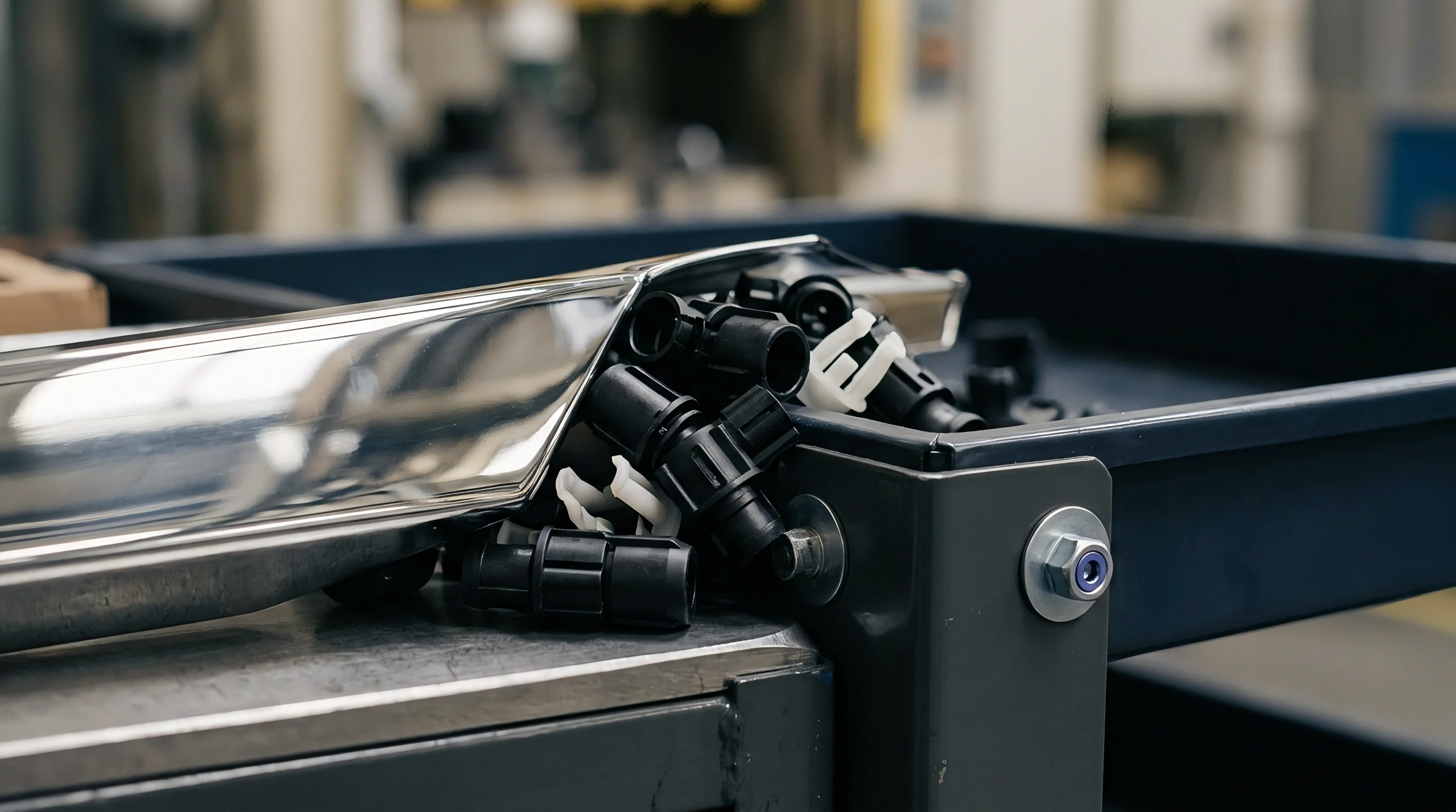
Steel

Cavity Metallurgy and Micro Feature Integrity
Precision micro injection moulding places extreme physical demands on tool substrate selection, requiring sub-micron grain structure, high thermal conductivity, and superior wear resistance under cyclic acoustic stresses. Conventional tool steels like AISI P20 or standard H13 display carbide segregation patterns exceeding five micrometers, creating structural defects during micro Electrical Discharge Machining (micro-EDM) and optical polishing. High-purity electro-slag remelted (ESR) martensitic stainless steels, such as DIN 1.2083 or powder metallurgy tool steels like CPM 10V, provide the uniform grain matrix needed to maintain edge sharpness on features below fifty micrometers.
Micro-resonator tooling incorporates high-frequency acoustic transducers operating between twenty and forty kilohertz directly into the core or cavity insert. These ultrasonic vibrations reduce melt friction along cavity walls during the injection phase, enabling complete filling of high-aspect-ratio features. The acoustic coupling between the resonator horn and the tool steel generates localized harmonic tension, accelerating fatigue failures if the steel lacks fracture toughness.
Tool designers must select substrates that combine a hardness above 54 HRC with an impact toughness exceeding fifteen Joules per square centimeter to withstand continuous transducer excitation.
Micro-moulding cavities utilizing ultrasonic resonator assist achieve fill depth improvements up to forty percent in aspect ratios exceeding twenty to one.
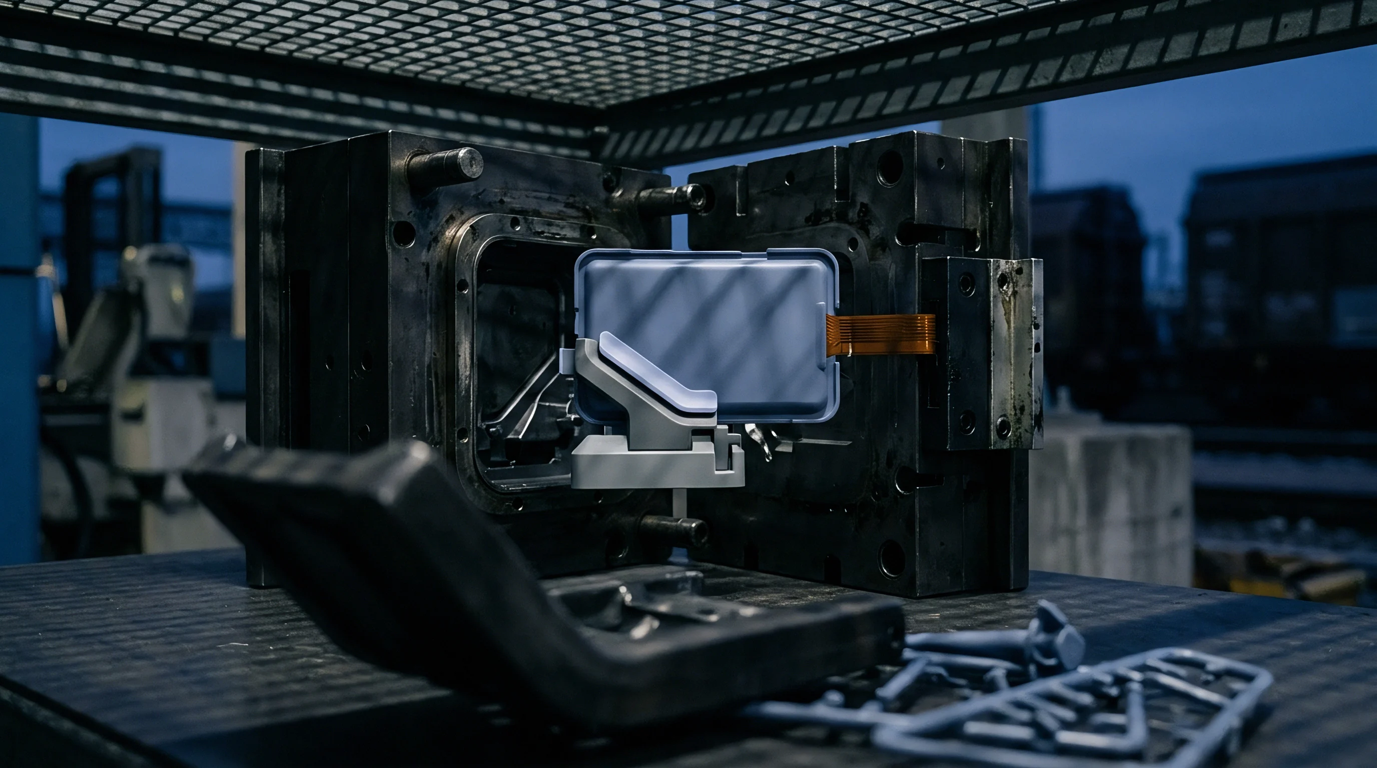
Micro Surface Machining and Acoustic Waveguide Integration
Fabricated micro-cavities demand surface roughness figures below ten nanometers Ra to permit part release without ejector pin damage. Traditional mechanical benching destroys fragile sub-millimeter cavity geometries; consequently, micro-milling with ultra-fine grain carbide cutters combined with specialized micro-EDM using zinc or tungsten wire electrode diameters down to twenty micrometers establishes the functional boundary of toolmaking accuracy. Toolmakers position the ultrasonic horn directly behind the cavity face, tuning the steel waveguide length to match half the acoustic wavelength of the driving transducer.
Improper waveguide length shifts the acoustic node away from the moulding surface, converting high-frequency longitudinal displacement into destructive lateral shear energy. When acoustic energy dissipates into the main mould base rather than the polymer melt, thermal spikes cause localized metal fatigue, parting line fretting, and early core pin breakage.
| Material Grade | Hardness (HRC) | Thermal Conductivity (W/m·K) | Polishing Limit Ra (nm) | Acoustic Attenuation (dB/m) |
|---|---|---|---|---|
| DIN 1.2083 ESR | 52 – 56 | 20.0 | 8.0 | 1.2 |
| CPM 10V Tool Steel | 58 – 62 | 21.5 | 12.0 | 2.8 |
| Titanium Grade 5 (Ti-6Al-4V) | 36 – 42 | 6.7 | 15.0 | 0.4 |
| Cobalt-Chromium MP35N | 48 – 54 | 11.2 | 5.0 | 0.8 |
Selecting an unsuited tool steel or miscalculating acoustic horn geometry leads to micro-fretting along cavity inserts, rapid corner rounding on thin-walled micro ribs, and total structural cleavage of core pins during volume production runs.

Impulse
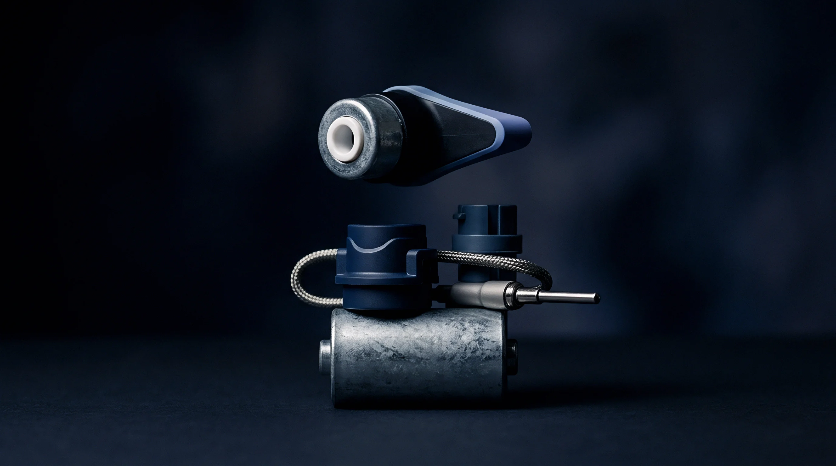
Rheological Transformations under Acoustic Excitation
Polymer flow within channels under one hundred micrometers wide encounters boundary layer friction that halts melt propagation before cavity fill completes. Introducing high-frequency energy directly into the molten front during injection alters the apparent viscosity of semi-crystalline polymers like liquid crystal polymer (LCP), polyetheretherketone (PEEK), and polyoxymethylene (POM). Acoustic cavitation within the melt stream disrupts intermolecular entanglements, dropping shear resistance without raising the global melt temperature past thermo-oxidative degradation limits.
Continuous vibration prevents premature skin freezing at the wall surface. Maintaining an active flow layer permits injection pressures below sixty megapascals on parts weighing less than one milligram, minimizing molded-in stresses that induce post-moulding optical orientation divergence or physical warping.
ISO 20753 specimen testing indicates high-frequency acoustic excitation reduces apparent viscosity by twenty-eight percent without changing polymer molecular weight.
Process Window Expansion and Phase Transformation Dynamics
Static micro-injection requires hyper-elevated barrel temperatures and injection speeds exceeding one thousand millimeters per second to fill micro-channels before thermal dissipation freezes the melt stream. Acoustic excitation decouple injection rate from fill capability, widening the stable process window on standard electric micro-moulding machines. The acoustic field maintains melt mobility through the filling phase and into the packing phase, delivering uniform pressure transmission across micro-geometries.
| Process Variable | Conventional Static Cavity | Ultrasonic Assisted Cavity | Active Core Dynamic Cavity |
|---|---|---|---|
| Melt Temperature (PEEK) | 410 °C | 375 °C | 380 °C |
| Peak Injection Pressure | 180 MPa | 110 MPa | 95 MPa |
| Minimum Wall Thickness Fill | 0.080 mm | 0.035 mm | 0.025 mm |
| Volumetric Shrinkage Variance | 1.8 % | 0.7 % | 0.3 % |
Tooling suppliers often attribute non-filling micro features to inadequate machine injection velocity when the actual cause is acoustic impedance mismatching between the horn and the cavity insert.
Kinematics
Active Core Driver Mechanics and Micro Stroke Control
Dynamic cavity volume manipulation provides direct volumetric control over polymer packing, eliminating reliance on runner-transmitted holding pressure. Active core actuation incorporates piezo-electric stack actuators or ultra-precise servo-hydraulic pins directly inside the tool plate assembly. During the initial injection phase, the core retracts slightly to widen the flow gate or cavity channel, allowing rapid fill under minimal flow resistance.
As the melt front reaches full cavity expanse, the core drives forward with sub-micron positional repeatability, compressing the semi-molten core to set final part dimensions.
Piezo-electric drivers generate stroke displacements between ten and one hundred micrometers with response times measured in sub-milliseconds. Hydraulic systems deliver longer strokes up to five millimeters but require specialized fast-acting proportional valves and closed-loop linear optical encoders to maintain micro-meter positioning accuracy under dynamic cavity pressure spikes.
- Initialize active core pin in the retracted pre-fill position prior to injection valve gate opening.
- Trigger injection unit stroke and monitor cavity pressure transducer readings until ninety percent volumetric cavity fill is registered.
- Energize piezo driver stack within two milliseconds of trigger signal to advance core pin through the compression phase.
- Hold core compression position against polymer thermal contraction until melt gate seal-off is achieved.
- Retract active core pin fractionally during cooling to release residual clamping force prior to main mould opening.
Core pin actuation timing aligned exactly with the peak cavity pressure phase prevents optical deformation and flash formation.
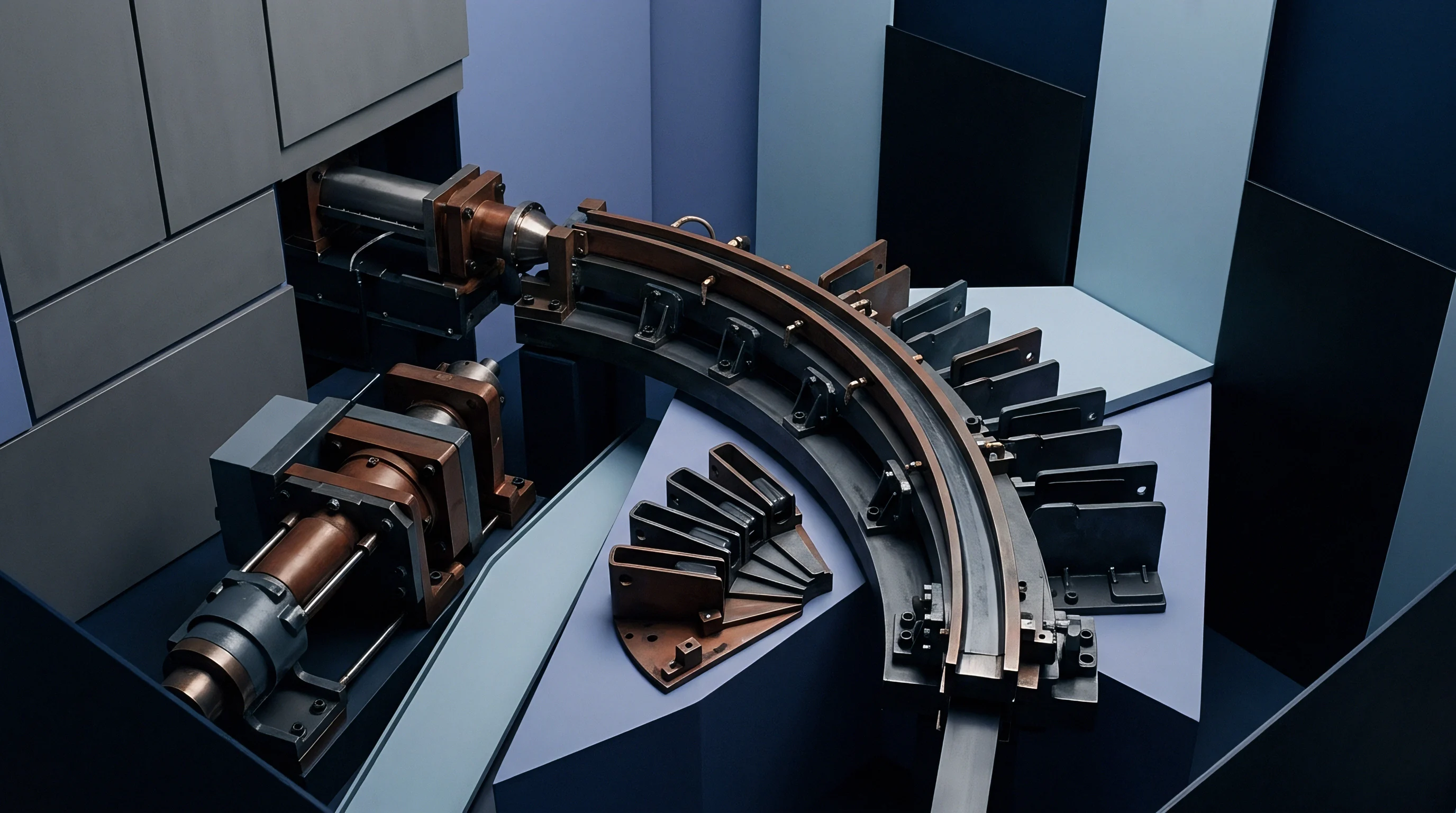
When Does Mechanical Core Actuation Outperform Piezo Electric Drives?
Piezoelectric actuators provide unmatched dynamic response and sub-micron positioning resolution, yet their absolute displacement limits restrict their application on parts requiring core movements greater than one hundred micrometers. High-aspect ratio core pins, deep internal blind holes, and complex undercut geometries demand mechanical core actuation driven by precision wedge slides or micro servo-spindles. Hydraulic micro-actuators deliver high force output over extended strokes, holding firm against injection pressures exceeding two hundred megapascals without mechanical deflection.
Sub-micron alignment between the core pin and the cavity sleeve relies on tight sliding fits below two micrometers. Thermal expansion differences between the active core assembly and the surrounding mould plate cause binding or galling during continuous temperature cycles if thermal stabilization circuits are omitted from the tool block design.
How do tool designers balance the higher frequency response of piezo stacks against the superior stroke length and force capacity of servo-hydraulic core pins in micro-resonator molds?
Tolerance
Shut-Off Design and Thermal Expansion Stack-Up
Holding dimensional consistency across micro-moulded components requires controlling tool plate clearance, shut-off angles, and core alignment within tight limits. Standard toolmaking tolerances of five micrometers result in flash formation when moulding low-viscosity resins; micro-moulding shut-off gaps must stay below two micrometers. Steel temperature control circuits must maintain mould frame temperature within plus or minus 0.5 degrees Celsius across an entire production run.
A shift of two degrees Celsius in a steel plate measuring one hundred millimeters induces two micrometers of thermal expansion, closing running clearances on active core pins and causing friction-induced binding.
Parting line design for active core tooling utilizes guided floating inserts, guided by pre-loaded roller cages rather than standard leader pins. Guided inserts eliminate lateral play during core actuation, maintaining concentricity between fixed cavity faces and moving core features.
- Pre-Load Verification checks that active core piezo stacks maintain constant mechanical force against retainer plates under peak thermal load.
- Guided Insert Clearance validates that sliding core sleeves retain a radial gap between 1.0 and 1.5 micrometers under maximum operating temperature.
- Optical Shut-Off Inspection confirms complete light blockage across mating steel sealing faces under target clamping force.
- Cavity Pressure Calibration verifies that internal piezoelectric transducer voltage outputs map linearly to real melt pressure during core advance.
Active cores moving during the cooling phase compensate for volumetric shrinkage in thick micro-features.
Metrology Verification and ISO Standard Adherence
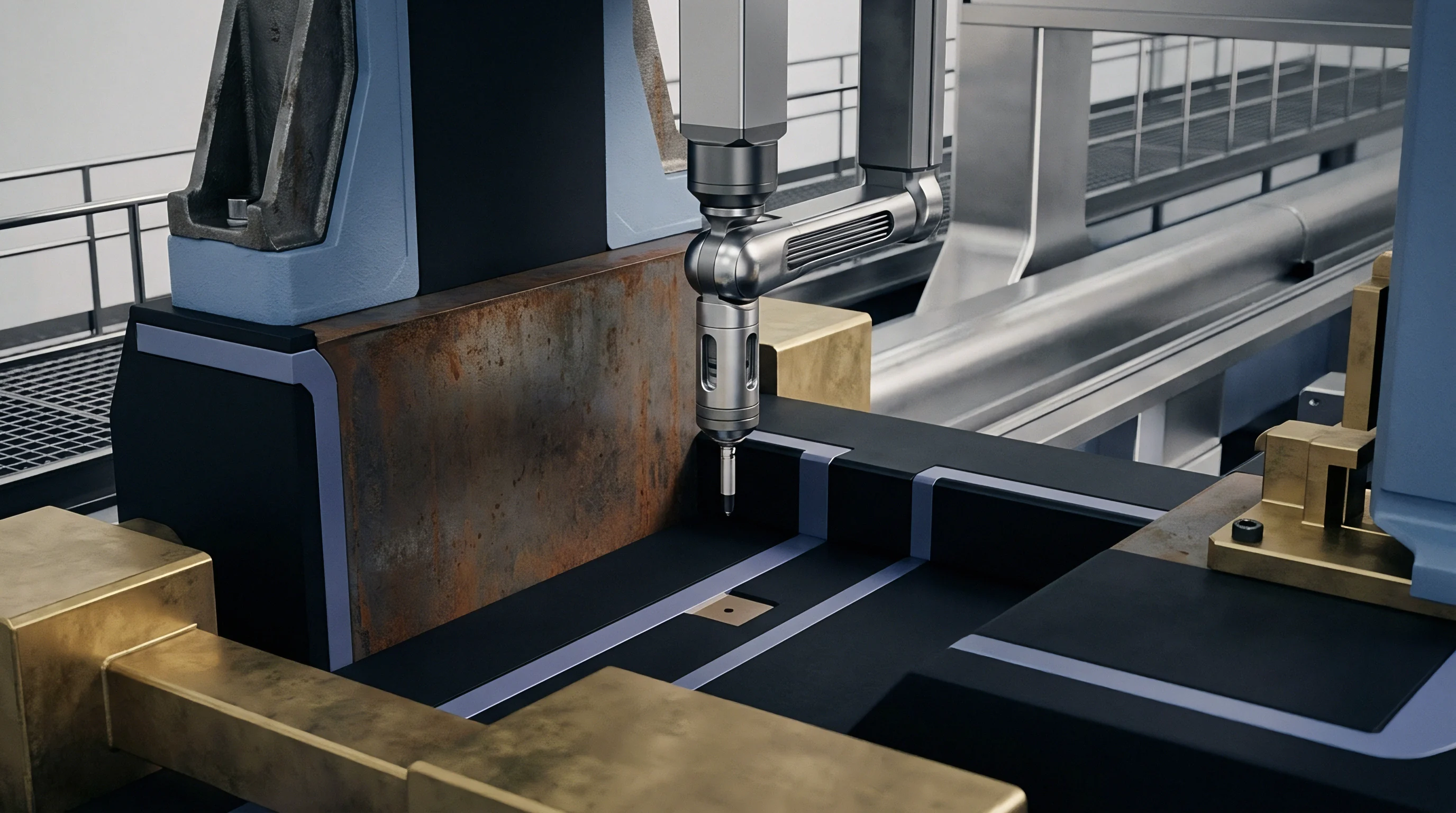
Direct physical measurement of micro-moulded components using contact coordinate measuring machines (CMM) frequently deforms fragile plastic micro-features, producing invalid inspection metrics. Non-contact optical systems, such as white-light confocal microscopy and micro-computed tomography (micro-CT), capture sub-micron surface topographies without mechanical part interference. DIN 16742 tolerance group NW1 governs non-optical micro-moulding dimensions, establishing allowable variances down to plus or minus seven micrometers on nominal dimensions under one millimeter.
Implementing active core actuation permits part dimensions to fall within tight tolerance classes like NW1 consistently across multi-cavity tools. By dynamically adjusting core forward position based on real-time cavity pressure feedback, the tool compensates for batch-to-batch polymer viscosity variations and minor press cycle variations.
DIN 16742 Annex A explicitly mandates that dimensional compliance for micro-moulded components must be verified following a minimum twenty-four-hour thermal conditioning period at twenty-three degrees Celsius and fifty percent relative humidity, transferring all risk of post-moulding environmental warpage to the component buyer if inspection occurs immediately press-side.

Valuation

Capital Amortization and Cavitation Economics
Commissioning an active core micro-moulding tool requires significant capital expenditure compared to conventional static tooling. Designing, machining, and integrating high-frequency acoustic transducers, piezoelectric actuators, and real-time closed-loop sensing arrays doubles or triples initial tool construction budgets. Single-cavity active core prototype tooling often costs more than a standard four-cavity static production tool.
Buyers justify this expenditure through unit price reductions achieved by eliminating secondary machining, reducing cycle times by twenty to forty percent, and minimizing scrap rates on complex micro-parts.
Cavitation decisions in active micro-moulding depend on control system complexity. High cavity counts increase driver electronics costs proportionally, as each cavity requires independent core position feedback and transducer tuning to ensure shot-to-shot uniformity across the mold face.
- Transducer Core Assemblies represent the single highest replacement component expense in high-frequency acoustic micro-tooling.
- Multi-Channel Piezo Controllers add significant hardware expense per cavity to press-side capital outlay.
- Precision Core Pin Inserts require frequent replacement budgets due to continuous sliding contact and micro-fretting wear.
- Optical Metrology Calibration Dossiers increase first-article inspection line item expenses during tooling sign-off.
| Tooling Architecture | Initial Tooling Capex Multiplier | Average Cycle Time (s) | Tool Life Expectancy (Shots) | Unit Maintenance Cost Contribution |
|---|---|---|---|---|
| Static 4-Cavity Standard | 1.0x | 8.5 | 1,000,000 | Baseline |
| Ultrasonic Assisted 4-Cavity | 1.8x | 5.8 | 750,000 | + 45 % |
| Active Core Hydraulic 2-Cavity | 2.2x | 6.2 | 500,000 | + 60 % |
| Active Piezo Core + Resonator 2-Cavity | 3.1x | 4.1 | 400,000 | + 110 % |
Calculating landed piece price requires amortizing active actuation sub-assembly replacement cycles directly into the machine hour rate, ensuring reserve funds cover piezo drive degradation before production interruptions occur.