Geometrically Balanced Runner Systems for Injection Molds
Geometrically balanced runner systems require dynamic melt rotation inserts to eliminate shear-induced thermal splits and ensure uniform cavity fill.


Symmetry
Equal distance from the primary sprue to every cavity gate forms the classic geometric foundation of multi-cavity injection tooling. Tooling drawings frequently assume that if every part nest sits at an identical linear vector from the machine center, polymer flow will automatically divide into equal volumetric streams. Steel plates milled with mathematically mirror-imaged channels present identical channel lengths, identical corner radii, and identical nominal cross-sections.
In unheated cold runner designs, this symmetry aims to deliver uniform pressure profiles and simultaneous cavity fill across the mold face.
Flow balance in multi-cavity molds governs part consistency across identical impression nests. When runner paths branch in symmetrical pairs, fluid friction along channel walls creates identical hydraulic resistance under idealized, Newtonian flow assumptions. Shot weight uniformity depends on this equalized resistance.
If one flow path presents higher resistance, its corresponding cavity fills slower, packs less, and exhibits higher volumetric shrinkage upon cooling. Steel retains heat.
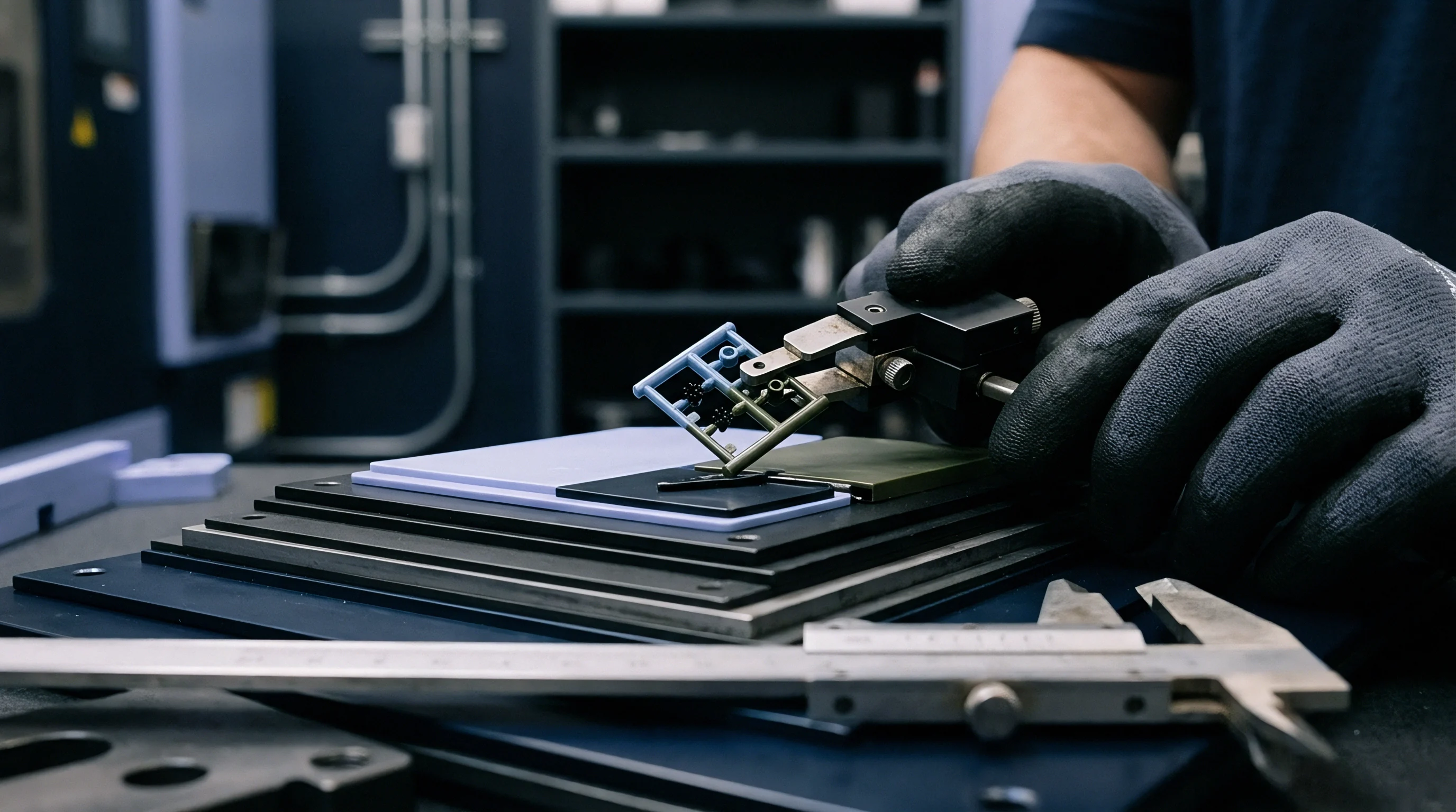
Identical Flow Path Lengths and Hydraulic Diameters
Layout drawings for multi-impression tooling often assume fluid moving through bifurcating channels behaves uniformly if spatial distances match. Hydraulic diameter calculations establish the flow capacity of non-circular runner geometries, mapping cross-sectional area to wetted perimeter. Maintaining identical hydraulic diameters across all primary, secondary, and tertiary channels prevents localized pressure drops that disrupt fill synchronization.
A channel cut two tenths of a millimeter shallow on one branch restricts flow significantly due to the fourth-power relationship between channel radius and volumetric flow rate in circular conduits.
Friction between molten polymer and temperature-controlled tool steel generates a stationary frozen layer along the runner perimeter. This frozen skin narrows the effective flow channel during the injection phase. In geometrically balanced layouts, equal channel dimensions yield uniform frozen skin thicknesses across every branch, provided thermal dissipation into the core and cavity plates remains uniform.
Viscosity shifts rapidly.
A two-step step-down ratio in runner diameter prevents excessive pressure drop while maintaining adequate melt velocity through secondary branches.
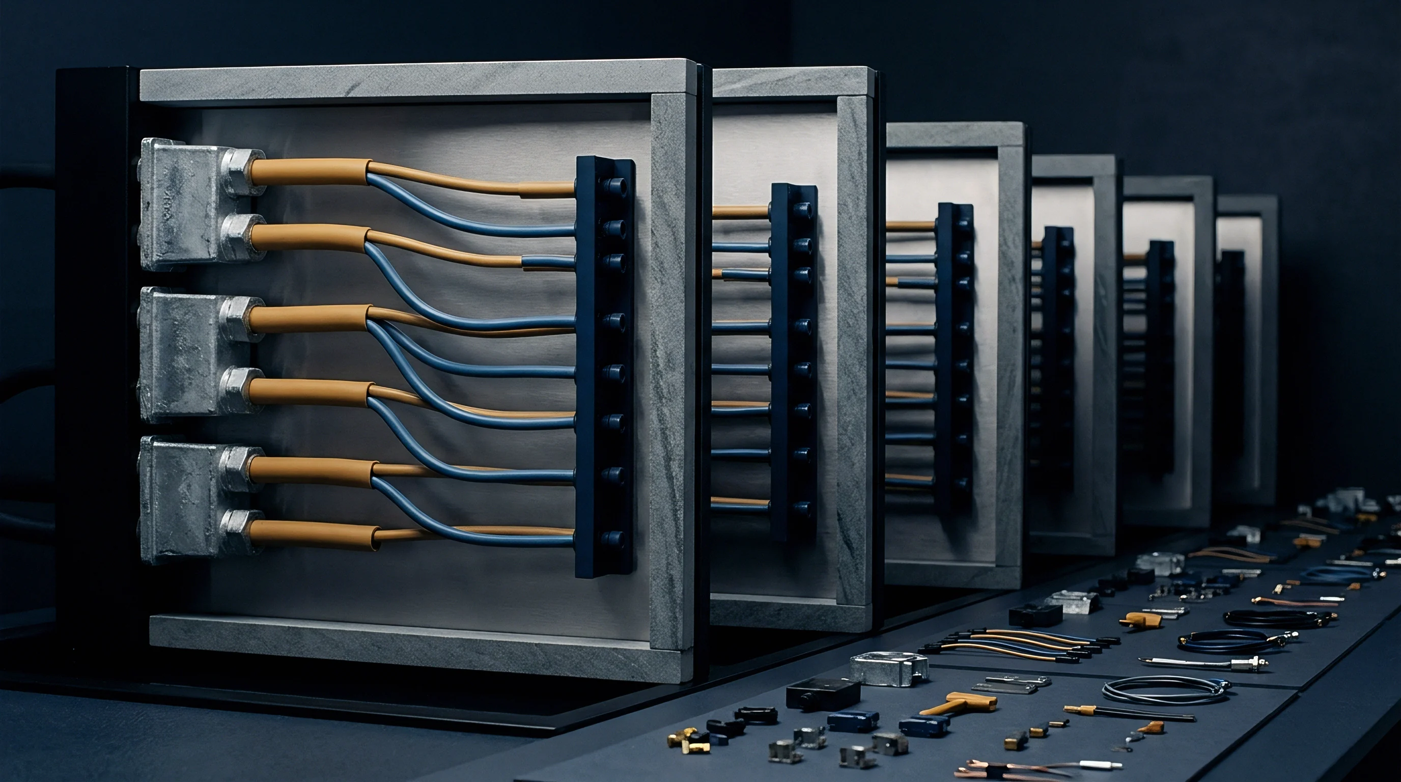
Layout Topologies across Multi Cavity Tooling
Arranging runner channels in polar or grid configurations determines both the steel block dimensions and the total volume of cold resin discarded per cycle. Standard layout patterns balance flow distances against the physical constraints of machine tie-bar spacing and ejector grid geometry. H-pattern designs replicate bifurcating splits to create identical geometric distances for eight, sixteen, thirty-two, or sixty-four cavities.
Radial or octopus patterns radiate channels directly from a central sprue to circular cavity arrays, offering equal path lengths with minimal total runner volume.
Fishbone layouts compromise pure path symmetry to maximize cavity count within narrow tool plates. In a fishbone design, parts feed off a central spine at varying distances from the main sprue. While fishbone configurations reduce steel plate costs, they introduce systemic fill imbalances due to unequal flow lengths.
True geometric balance demands branching structures where every path from machine nozzle to part gate contains an identical sequence of turns, lengths, and cross-sectional reductions.
| Layout Topology | Flow Path Symmetry | Steel Footprint Efficiency | Pressure Drop Characteristics | Relative Scrap Volume |
|---|---|---|---|---|
| H-Pattern (16-Cavity) | Fully Symmetric | Moderate | Predictable / Step-wise | High |
| Radial / Star | Fully Symmetric | Low (Circular Array) | Minimal / Direct Path | Moderate |
| Fishbone | Asymmetric | High | Variable per Cavity | Low |
| Modified Octagonal | Near Symmetric | High | Moderate | Moderate |
Evaluating multi-cavity layouts requires mapping the complete runner volume against the total shot weight of the molded parts. Oversized runners maintain pressure transmission but extend cycle times by requiring longer cooling phases before ejection. Undersized runners generate excessive shear heating and drop line pressure before the cavity gate seals.
Geometric symmetry serves as the necessary baseline, yet spatial equality alone fails to guarantee equal filling under real injection speeds and non-Newtonian polymer melt behavior. A layout designed solely on linear spatial balance ignores thermal gradient development during high-speed injection, leaving final cavity balance subject to local viscosity shifts across the melt stream.
Physics
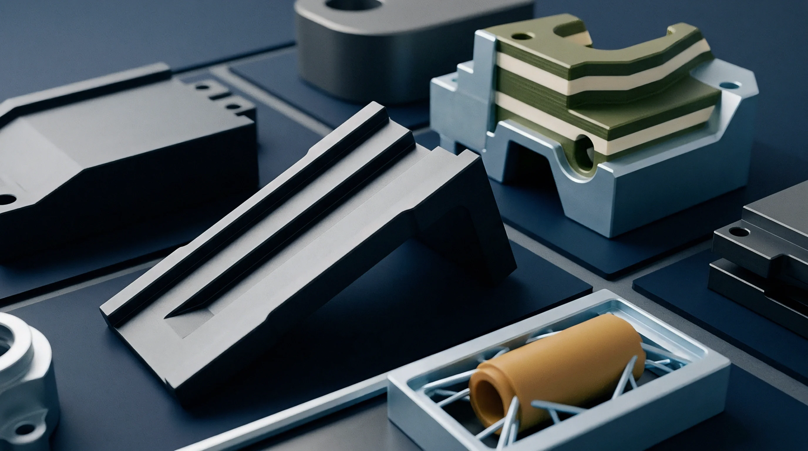
Polymers traveling through cold runner channels undergo high shear rates adjacent to non-moving steel surfaces, creating steep temperature and viscosity profiles across the flow cross section. Molten plastic behaves as a non-Newtonian, shear-thinning fluid. Near the channel wall, rapid velocity gradients shear polymer chains, lowering local viscosity and generating intense frictional dissipation.
In the central core of the runner, shear rates approach zero, allowing resin to maintain higher viscosity and cooler temperatures. This separation into thermal and rheological layers fundamentally alters flow behavior at downstream branch points.
When high-velocity resin encounters a tee-junction in a runner network, the outer sheared layers split differently than the core fluid. The fluid entering the inner bend of the new branch consists primarily of high-shear, low-viscosity material from the perimeter of the parent channel. Fluid entering the outer side of the new branch originates from the higher-viscosity core region.
Fill balance determines yield.
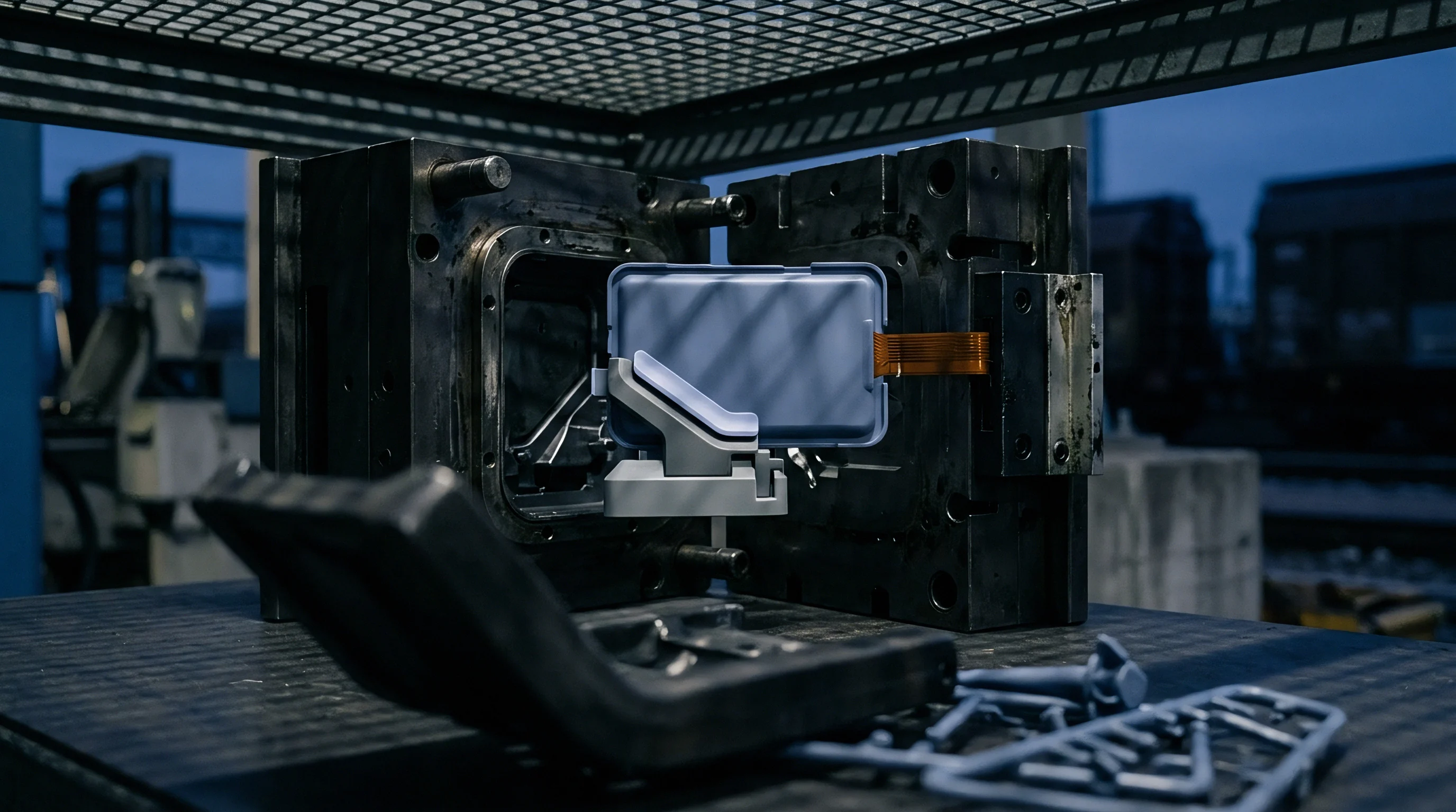
Shear Rate Variations across Mold Junctions
When high-velocity resin negotiates a ninety-degree turn at a channel intersection, the hot laminate layers concentrate along the inner wall. As the flow splits into secondary channels, this asymmetrical distribution of shear-heated polymer forces material of unequal viscosity into nominally identical flow streams. The secondary channel receiving a higher proportion of sheared, warm polymer offers less flow resistance.
Resin moves faster through this path, filling its destination cavities prior to adjacent cavity nests fed by cooler, higher-viscosity polymer streams.
Shear rate varies inversely with the cube of channel radius under constant volumetric flow. Secondary channel reductions increase local shear rates, exacerbating thermal gradients generated at primary runner intersections. In an eight-cavity H-pattern layout, the inner four cavities consistently receive hotter material than the outer four cavities, despite flawless geometric symmetry on the tool drawing.
Inner cavities pack early.
A thermal variance of seven degrees Celsius across outer runner walls increases cavity fill imbalance by up to twelve percent in semi-crystalline resins.

Thermal Asymmetry inside Geometrically Uniform Channels
Melt entering downstream branching circuits inherits non-uniform temperature profiles, resulting in outer cavities receiving cooler, higher-viscosity fluid than inner cavities. Cold slug wells capture degraded resin. This phenomenon, known as shear-induced melt imbalance, causes significant dimensional and weight variations across identical parts produced in a single press stroke.
Inner cavities experience higher peak cavity pressures, leading to flash, over-packing, and tight ejection clearance, while outer cavities suffer from sink marks, short shots, and lower volumetric density.
Gate freeze controls part weight. When inner gates remain open longer due to elevated local melt temperatures, density variations solidify into permanent part-to-part discrepancies. Standard geometric balancing techniques cannot offset shear-induced thermal asymmetry, as the thermal stratification develops dynamically within the fluid during the injection stroke itself.
Shear-induced flow disparities trigger predictable defect patterns across multi-impression tooling:
- Short-Shot Tendencies occur in outer cavities where cooler, higher-viscosity resin encounters excessive flow resistance before complete volume filling.
- Part Flash develops on inner cavities as low-viscosity melt fills prematurely and experiences excessive packing pressure.
- Dimensional Variance spreads across part lots when cavity-to-cavity weight distributions exceed acceptable statistical process limits.
- Warpage and Distortion manifest in multi-gated single parts due to uneven stress distribution caused by asymmetrical fill rates.
- Gate Vestige Shear Tears result from delayed gate freeze-off times in cavities fed by hyper-sheared flow streams.
Addressing these thermal and rheological splits demands looking beyond drawing-board spatial symmetry. Process setters often attempt to correct filling non-uniformities by adjusting barrel temperatures or injection velocity profiles, but these global press adjustments alter the overall melt index without resolving localized thermal splits. Why does shear imbalance persist in tools designed to strict spatial tolerances?
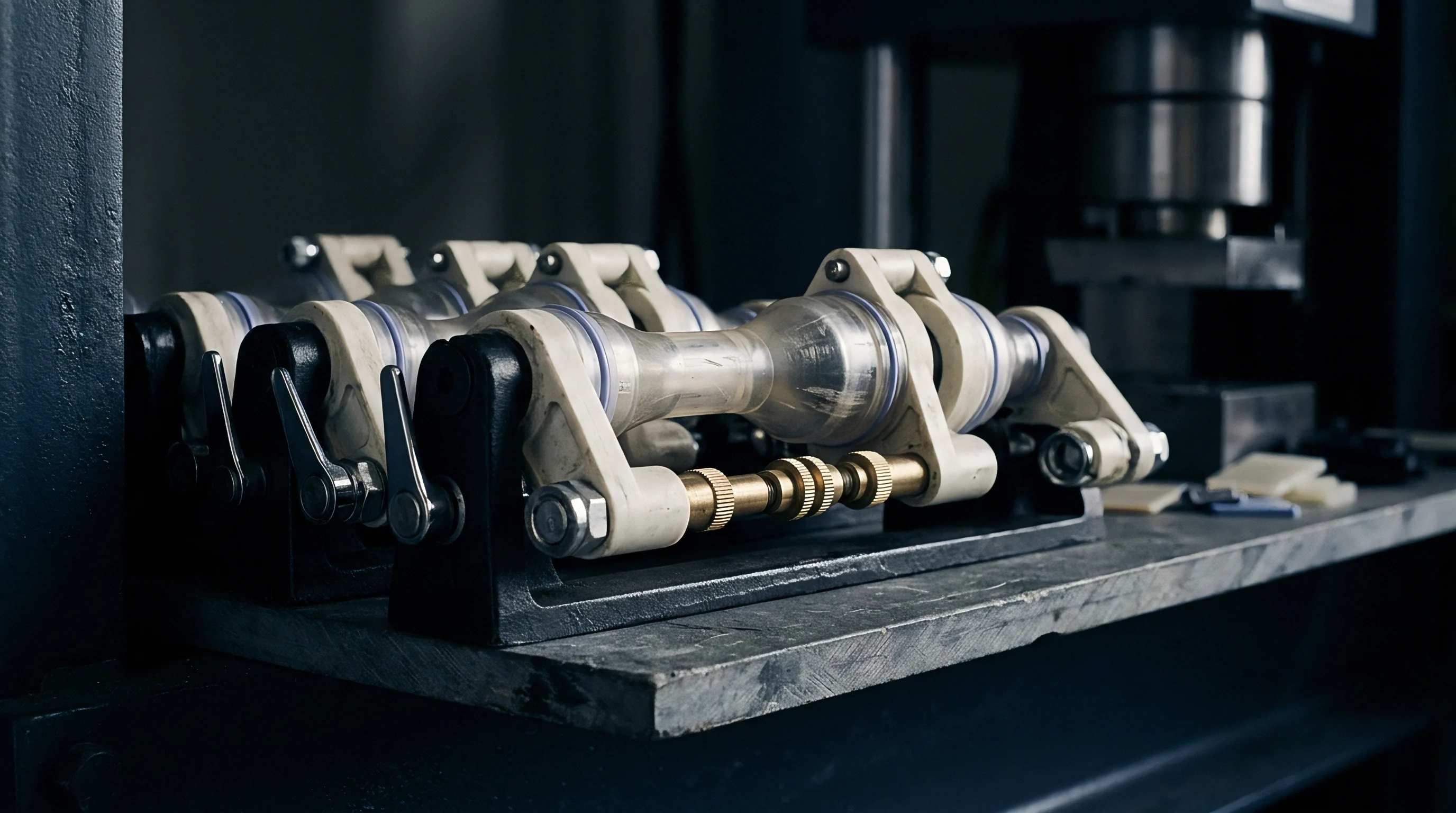

Channel
Selecting runner cross-sectional shapes hinges on balancing pressure transmission efficiency against the cooling time of the solidified plastic sprue and branch network. The cross-sectional geometry establishes the ratio of surface contact area to volumetric flow capacity. Minimizing heat loss to the mold steel while maintaining manageable scrap volume requires selecting profiles that optimize hydraulic radius without introducing machining complexity inside the mold plates.
Full-round runners deliver peak theoretical efficiency by minimizing perimeter contact per unit volume. However, full-round channels require accurate three-axis milling across both mold halves, increasing toolmaking labor and risk of parting line mismatch. Modified trapezoidal profiles, machined into a single mold plate with a five-degree draft angle and rounded bottom corners, approximate full-round fluid mechanics while simplifying plate alignment and reducing tool manufacture expense.
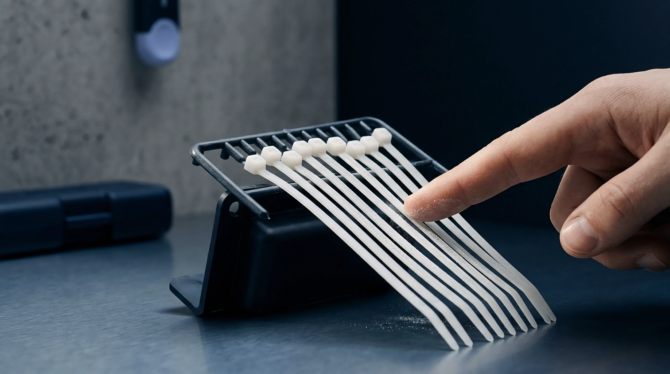
Cross Sectional Profile Efficiency and Pressure Drop
Full-round geometries yield the lowest surface-to-volume ratio, minimizing friction loss and thermal transmission into the cooled cavity plates. Half-round runners, while simple to machine into a single plate, present a high surface area relative to volume, causing rapid heat dissipation and severe pressure loss. Parabolic and modified trapezoidal shapes provide a practical compromise for tooling construction, offering ninety to ninety-five percent of the flow efficiency of full-round profiles.
Calculating pressure drop through runner branches uses modified fluid equations accounting for non-Newtonian power-law behavior. The volumetric flow rate Q passing through a circular channel of radius r under shear-thinning conditions depends on the polymer consistency index K and power-law index n:
dP = (2 K L / r) ((3 n + 1) / (n pi r^3))^n Q^n
Step-down ratios between primary, secondary, and tertiary branches preserve fluid velocity while preventing excessive pressure drops across the runner layout. Reducing cross-sectional area after each bifurcation point maintains uniform shear rates across the system. A typical design targets a cross-sectional area reduction of thirty to forty percent per branch level.
| Cross-Section Profile | Machining Requirement | Relative Pressure Efficiency | Surface-to-Volume Ratio | Cooling Rate Impact |
|---|---|---|---|---|
| Full-Round | Two Mold Plates (Matched) | 100% (Baseline) | Lowest (4 / d) | Slowest (Governs Cycle) |
| Modified Trapezoid | Single Mold Plate | 92% – 95% | Moderate | Moderate |
| Parabolic | Single Mold Plate | 88% – 91% | Moderate to High | Moderate |
| Half-Round | Single Mold Plate | 65% – 70% | Highest | Fastest (High Drag) |
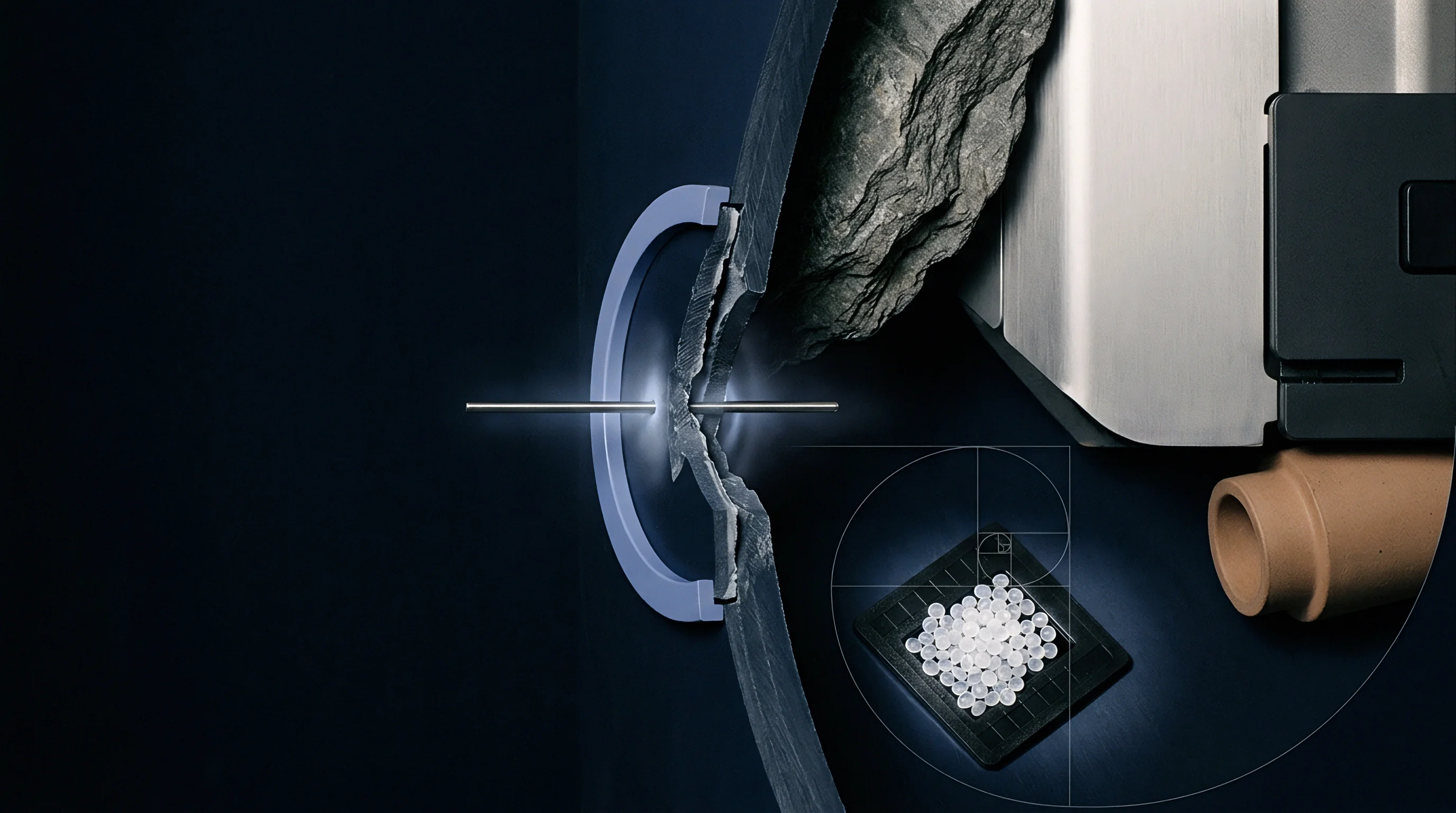
How Does Shear Imbalance Override Geometric Symmetry?
Non-Newtonian fluid behaviors cause melt split at high velocity to segregate into zones of differing viscosity, breaking volumetric fill uniformity. As polymer flows through a primary runner, friction generates a concentric band of hot, sheared resin near the outer wall surrounding a cold core. Upon entering a T-junction split, the inner side of both branch channels receives material exclusively from the sheared outer layer, while the outer side receives core material.
Subsequent splits down the branch network amplify this asymmetric distribution, directing warm, fast-flowing resin to specific cavities while adjacent cavities receive cool, sluggish resin.
Flash occurs at high pressure. Designing runner systems without addressing this shear separation leaves tools vulnerable to narrow operating windows press-side. To quantify the impact of runner sizing and layout on sizing calculations, consider a typical engineering resin calculation sequence.
To dimension a geometrically balanced cold runner network for an 8-cavity tool, follow this analytical procedure:
- Calculate the nominal wall thickness of the part moulding and establish the primary runner diameter equal to the maximum part wall thickness plus one point five millimeters.
- Determine the flow length ratio from the main sprue to the furthest cavity nest to confirm line pressure capacity.
- Apply a area reduction factor of zero point seven to size secondary runner branches relative to the primary supply channel.
- Set cold slug well depths at all tee-intersections to twice the diameter of the branching runner line to capture the leading cold melt front.
- Verify that the total volume of the runner network remains under twenty percent of the combined injection unit shot capacity.
DIN 16742 Tolerance Group TG4 dictates that cavity-to-cavity dimension variances across a mold layout cannot exceed zero point zero three millimeters for precision components.
Consider an operational case study involving a 16-cavity tool producing medical syringe barrels from poly-propylene. Assume an injection flow rate of forty-five cubic centimeters per second, a primary runner length of one hundred twenty millimeters, and a secondary branch length of forty-five millimeters. If primary runner diameters are misaligned by zero point one5 millimeters due to tool steel polishing errors, local flow resistance shifts by eleven percent.
This shift alters gate freeze timing by zero point eight seconds between cavity pairs, driving scrap rates upward due to weight variance across the production lot. Sizing channels without strict verification of machining tolerances guarantees unrepeatable cavity yield.

Correction
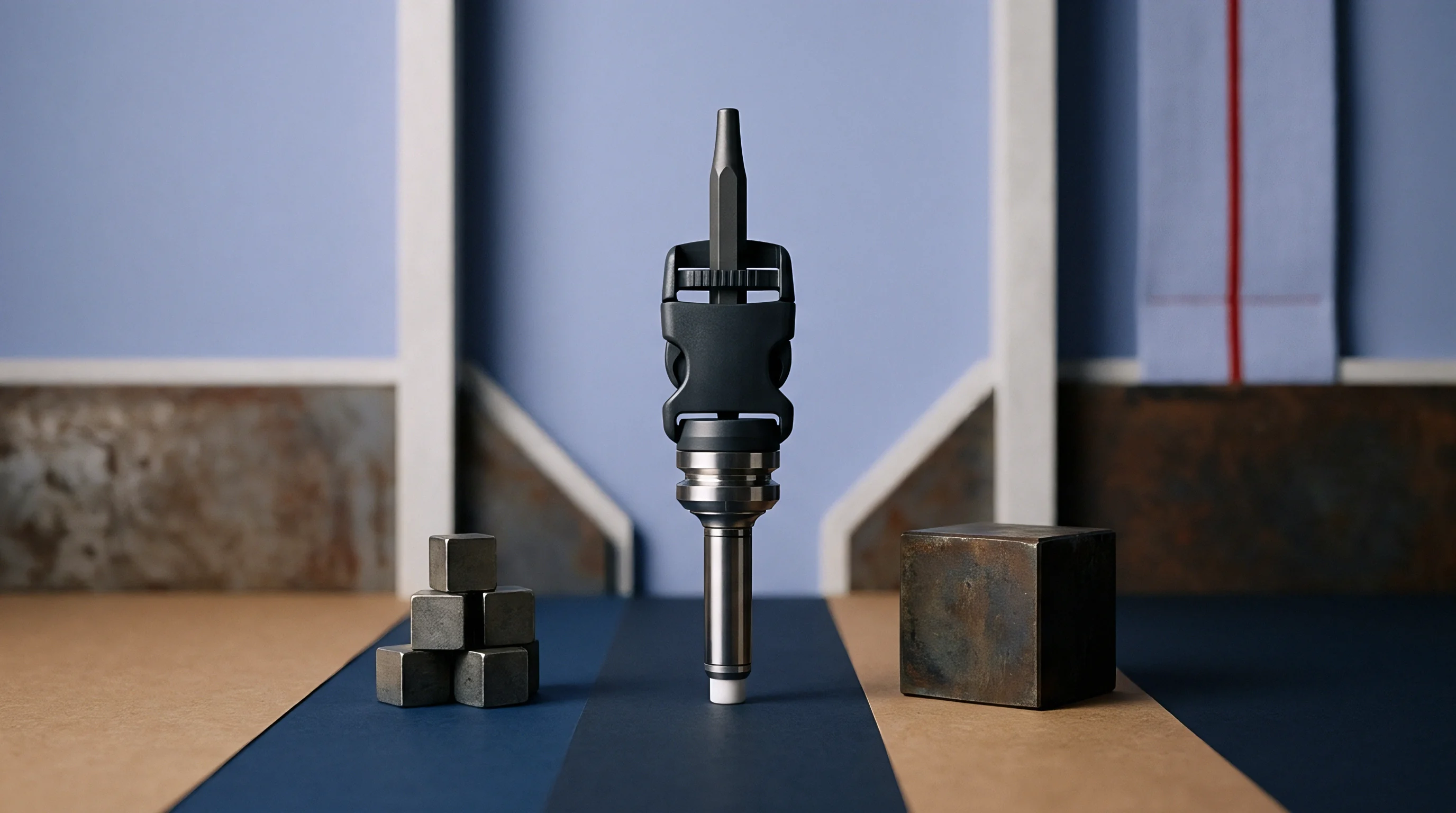
Engineers eliminate dynamic filling disparities by physically rotating the melt stream prior to downstream branching. Modifying tool steel to compensate for rheological melt separation shifts shear layers into symmetrical distributions before the fluid reaches secondary split nodes. Rather than altering gate dimensions, which only remedies flow resistance at a single operating viscosity, geometric melt manipulation re-establishes true thermal and viscosity balance across the whole process window.
Melt flipping channels flip the cross-sectional fluid profile ninety degrees between primary and secondary branch junctions. By forcing the hot, sheared outer layer of polymer into the core of the downstream channel, the fluid entering subsequent splits presents equal viscosity on both the left and right sides of the branching node. Pressure drops across sharp turns.

Melt Flipping and Homogenization Inserts
Custom runner inserts reposition the high-shear outer boundary layer into the central core of the fluid channel before the secondary split. Proprietary insert configurations use precise three-dimensional geometry to turn the fluid stream, ensuring that high-shear, low-viscosity material is split evenly between sub-branches. This physical homogenization eliminates the root cause of shear-induced filling imbalance without relying on gate modification or artificial thermal zones.
Integrating melt-rotation inserts into cold runner mold plates requires minimal steel removal and can be retrofit into existing imbalanced tooling. Positioned directly at the first primary bifurcation point, these inserts redistribute thermal layers, equalizing cavity fill times to within one to two percent variance across thirty-two or sixty-four impression tools. Dimensional variance drives scrap rates.
| Correction Method | Mechanism | Process Window Width | Tooling Modification Cost | Viscosity Sensitivity |
|---|---|---|---|---|
| Melt Rotation Inserts | 3D Flow Path Stratification Shift | Wide (Viscosity Independent) | Moderate (Insert Retrofit) | Insensitive |
| Differential Gate Tuning | Localized Steel Resistance Adjustment | Narrow (Viscosity Dependent) | Low (Steel Erosion) | Highly Sensitive |
| Variable Runner Sizing | Branch Diameter Alteration | Narrow | Moderate (Re-milling) | Sensitive |
| Localized Thermal Control | Segmented Heater Cartridges | Moderate | High (Electrical Setup) | Moderate |

Artificial Balancing through Steel Adjustments
Toolmakers often resize individual gate lands or alter channel diameters to force equal volumetric filling rates across all impression nests. This practice, known as steel balancing or artificial balancing, alters local hydraulic resistance to counter thermal imbalances. Machine operators adjust gate land lengths or gate cross-sections using wire EDM to choke flow to fast-filling inner cavities while opening flow to slow-filling outer cavities.
Artificial balancing fixes fill symmetry for only one specific set of processing conditions. If injection speed, melt temperature, or material lot viscosity changes, the artificial balance fails. Lowering injection velocity reduces shear heating, which alters the viscosity differential between channels and causes previously choked cavities to short-shot.
Dynamic balance modifications using melt rotation preserve system equilibrium regardless of press parameter shifts.
Selecting correction strategies for multi-cavity tooling involves structured design decisions:
- Melt Rotation Inserts provide permanent, process-independent balance by geometrically re-orienting shear layers before secondary branches.
- Sub-Runner Diameter Tuning compensates for predictable pressure drops in extended layouts but remains sensitive to resin viscosity shifts.
- Differential Gate Sizing corrects fill timing at specific injection rates but narrows the acceptable molding window across material lots.
- Rheological Flow Simulation models shear-induced thermal splits prior to steel cutting, allowing pre-tooling placement of rotation nodes.
Runner volume exceeding twenty percent of total shot weight degrades mold profitability through extended cooling times and regrind handling.
Tooling vendors often claim that cavity imbalance can be dialed out entirely by fine-tuning gate depths down to five micrometers. Experienced setters recognize this excuse as a temporary patch that shifts the burden of thermal balance onto press operators, who must then hold artificially narrow viscosity windows on every incoming resin lot.

Economics
Calculating the financial return of multi-cavity tooling balances initial machining capital against recurring regrind losses and unit manufacturing cycle seconds. Cold runner networks contribute directly to unit price through raw material consumption and extended cooling times. When a mold runner volume represents thirty percent of total shot weight, processing costs rise due to plasticizing energy requirements, regrind remelt degradation, and longer press occupancy per good part produced.
Regrind degrades polymer chain length. Virgin material blended with high percentages of re-granulated runner plastic exhibits reduced mechanical properties, lower impact strength, and unpredictable Melt Flow Index (MFI) shifts. In regulated medical or automotive applications, strict quality standards cap regrind usage at ten to fifteen percent, forcing excess runner scrap to be sold at a loss or disposed of as industrial waste.

Runner Weight Impact on Landed Part Cost
Excess material frozen inside sprue paths directly inflates resin expenditure per piece when regrind ratios stay strictly capped by regulatory limits. Optimizing runner channel diameters reduces runner mass without inducing excessive pressure drop or gate freeze prematurely. Sinking capital into high-precision, geometrically and dynamically balanced runner designs reduces total shot weight, unlocking significant raw material cost savings over multi-million-cycle production runs.
Cycle time in cold runner tooling is frequently dictated by the thickest section of the primary runner channel rather than the wall thickness of the molded part. If a part wall measures one point five millimeters but the primary sprue runner node measures six millimeters, the machine operator must hold clamp dwell until the runner solidifies sufficiently to permit clean ejection. Tooling modifications carry high costs.
| Tool Configuration | Initial Tooling Capital Expenditure | Cycle Time (Seconds) | Scrap / Scrap Rate (%) | Landed Part Cost (per 1,000 units) |
|---|---|---|---|---|
| 32-Cavity Unbalanced Fishbone | $110,000 | 14.5 | 4.2% | $48.50 |
| 32-Cavity Geometrically Balanced | $135,000 | 13.0 | 2.1% | $42.10 |
| 32-Cavity Dynamically Balanced (Melt Flipped) | $148,000 | 11.8 | 0.3% | $37.80 |

Process Window Breadth and Cavity Yield
Imbalanced multi-cavity molds restrict operating parameters, forcing press setters to run elevated pack pressures that induce flash on inner cavities while outer cavities sink. Operating near the extreme boundaries of the process window increases scrap rates, causes part sorting labor, and elevates mold repair costs due to flash-induced parting line indentation. A dynamically balanced tool widens the process window, enabling stable operation across minor resin viscosity shifts without generating out-of-spec dimensions.
Validating tool qualification requires establishing documented cavity-to-cavity consistency across production lots:
- Cavitation Verification Dossier detailing shot weight variance across all nests using short-shot fill series protocols under ISO 294 guidelines.
- Statistical Process Capability Studies proving part dimensional Cpk values equal to or exceeding one point six seven across consecutive shift runs.
- Pressure Drop Mapping recording hydraulic transfer loss from machine transducer to secondary runner channel tips.
- Regrind Limits Specification Clause defining maximum allowable re-melt ratios and mechanical property degradation thresholds.
Under standard tooling procurement master agreements, clause 4.2 dictates that cavity-to-cavity part weight variation within a multi-cavity mold layout shall not exceed plus or minus one point five percent across a continuous eight-hour run, transferring the financial burden of steel balance rework directly to the toolmaker until qualification metrics land inside specification.