Establishing Base Reference Points on Flexible Injection Molded Components
Establishing reference points on flexible injection molded parts relies on ISO 10579 restrained-state fixturing, datum target pads, and optical metrology.


Datum
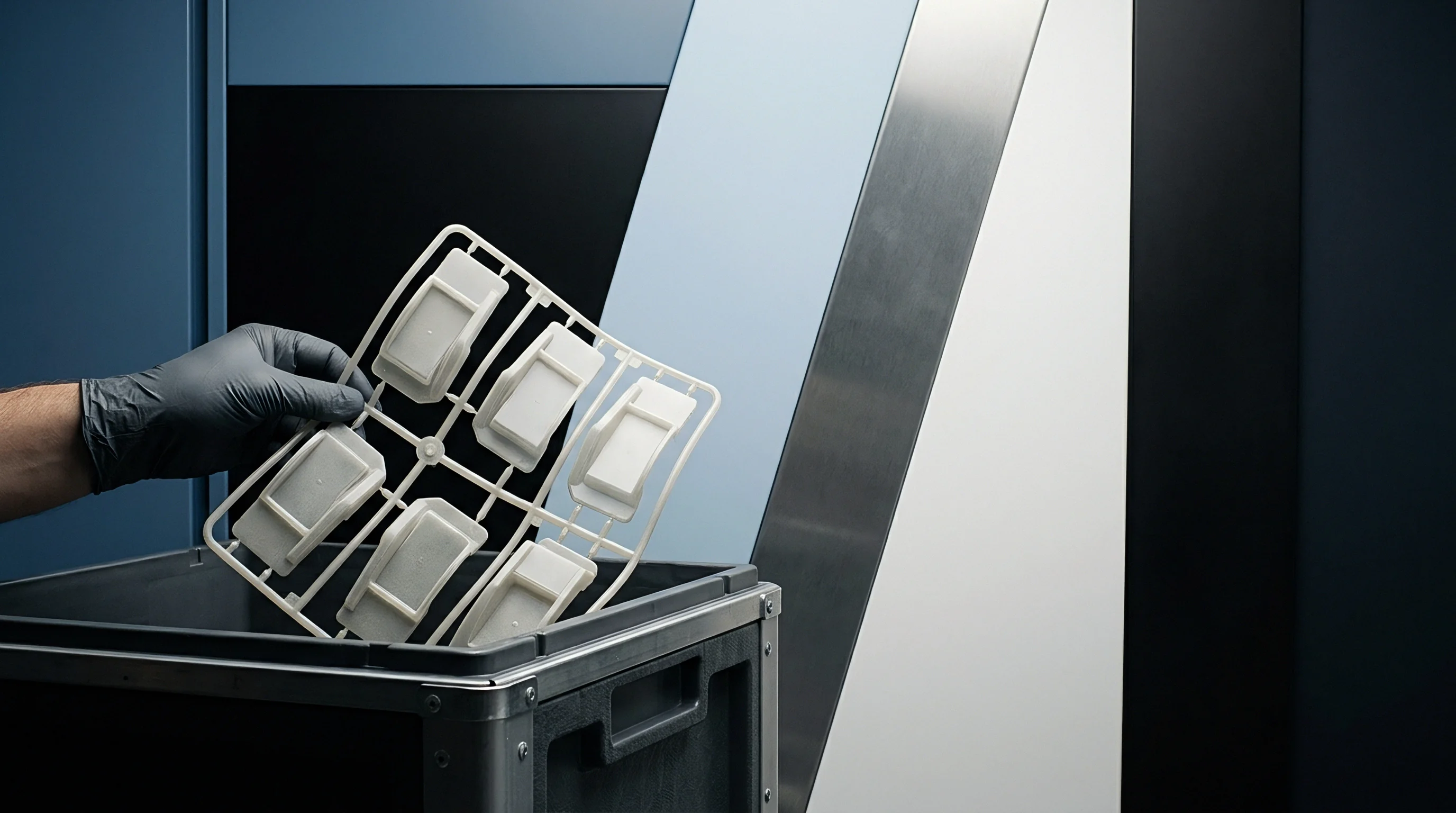
Rigid Alignment Rules Applied to Elastomeric Bodies
Injection molded thermoplastic elastomers yield under probe pressures that standard steel or aluminum components resist without measurable distortion. When applying standard geometric dimensioning and tolerancing according to ASME Y14.5 or ISO 5459, planar surfaces serve as primary reference features. Flexible polymers such as thermoplastic vulcanizates (TPV) or thermoplastic polyurethanes (TPU) ranging from 40 Shore A to 55 Shore D flex under gravity and localized point loads.
Establishing a rigid three-two-one reference frame directly on an unconstrained flexible surface introduces instantaneous dimensional error into quality inspection.
Part drawings that specify flat primary datums without qualification force quality inspectors to guess where the part surface rests during measurement. Gravity bends soft features. A 200 mm long automotive door seal profile molded from 65 Shore A EPDM/PP blend sags up to 3.5 mm under its own mass when supported only at two end points.
Placing the component on a granite surface plate creates variable contact profiles based on local sink, residual thermal strain, and part orientation. Quality control teams attempting to establish a primary datum plane across a curved, flexible surface record gauge repeatability and reproducibility (R&R) values exceeding forty percent. Steel holds its shape.
Flexible plastic adopts the shape of whatever surface it touches.
Primary datums on flexible moldings require surface target pads to prevent localized deflection during coordinate measurement.
Target pads replace continuous surface definitions on flexible components. Specifying defined spherical or planar target pads limits mechanical contact to controlled, high-rigidity regions such as internal rib intersections or reinforced mounting bosses. ISO 10579 explicitly provides the framework for non-rigid part specification, allowing drawing authors to define free-state condition versus restrained-state condition.
Without target pad declarations, tactile coordinate measuring machine (CMM) probes collapse the part geometry at the instant of touch trigger, shifting the calculated datum reference frame relative to actual part features.

Contact Deflection and Target Pad Area Mechanics
Tactile inspection forces generate localized compressive strain in low-durometer elastomers. Standard touch-trigger CMM probes exert contact forces between 0.05 N and 0.20 N. While negligible on stiff thermoplastics like glass-filled nylon, a 0.10 N force applied by a 2 mm diameter ruby stylus onto a 50 Shore A TPE depresses the surface by 0.12 mm before registering a coordinate point. The resulting measurement understates true part dimensions.
- Target Pad Indentation occurs when small probe contact areas concentrate measuring force beyond the elastic yield threshold of soft polymer grades.
- Datum Plane Tilting develops when asymmetric deflection across three target points rotates the calculated Cartesian coordinate frame relative to functional cavity axes.
- Free State Sag distorts secondary feature positions before tactile or optical inspection routines begin execution on unconstrained moldings.
- Viscoelastic Creep occurs when continuous fixture clamping pressures cause progressive time-dependent wall thickness reductions during extended inspection runs.
Engineers continue to debate whether a three-point planar contact interface provides sufficient stability for parts with Shore A hardness values below forty.
Clamp
Restrained State Inspection Fixtures under ISO 10579
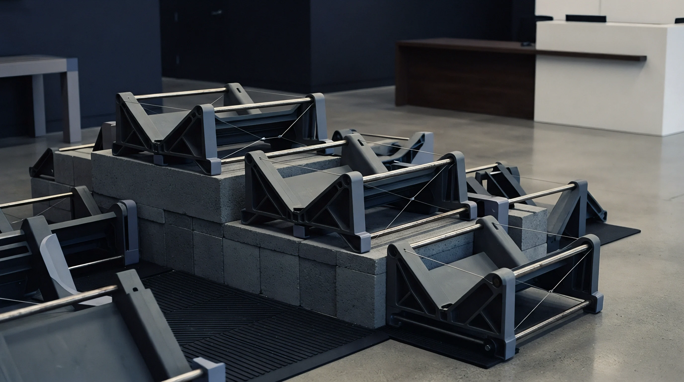
Parts molded from flexible resins distort under gravitational load and residual molding stresses when removed from the mold cavity. ISO 10579 mandates that drawing callouts for flexible parts state whether dimensions apply in the unconstrained free-state or in a restrained condition simulating final assembly. Restrained inspection requires custom mechanical tooling designed to hold the component against its defined base reference points without inducing artificial structural deformation.
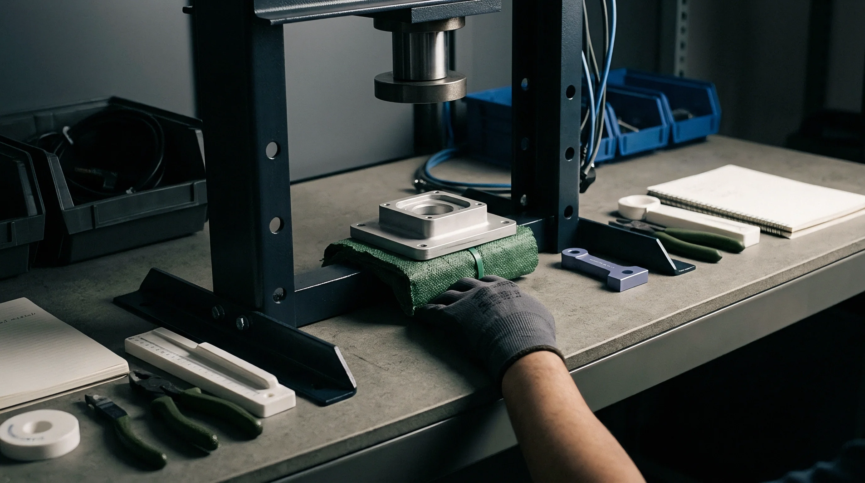
Clamping systems must replicate assembly conditions without crushing adjacent flexible walls. Mechanical toggle clamps, vacuum nests, and magnetic holding blocks serve as primary restraint mechanisms. A miscalculated clamping force alters the part layout, pushing wall features outside design tolerance bands.
When designing restraint tooling for a 70 Shore A TPU housing, applying toggle clamp forces above 15 N along the perimeter flange induces localized wall bowing of 0.45 mm across adjacent seal channels. Vacuum nests eliminate side loads. Vacuum fixtures distribute holding force uniformly across contoured bottom surfaces, maintaining part orientation against reference pins while eliminating localized strain spikes.
Per ISO 10579 specifications, dimensions marked with the NR symbol apply only when the part is held in its customized assembly fixture.
Restraint pressure application requires strict sequencing. Primary datum target pads engage first under low force. Secondary and tertiary locating pins align the perimeter without pre-loading flexible walls in shear.
Torque-limiting screws or calibrated pneumatic actuators maintain repeatable force application across consecutive inspection cycles, ensuring operator independence during batch release audits.
Vacuum Nest Differential and Fixture Force Balancing
Vacuum fixtures require precise calculation of effective surface area and differential air pressure to prevent part dimpling. Excessive vacuum levels pull thin elastomeric skins into internal suction ports, creating localized depressions that optical scanners misinterpret as mold sink marks.
| Material Durometer | Probe Stylus Diameter (mm) | Applied Contact Force (N) | Surface Area of Pad (mm²) | Measured Deflection (mm) |
|---|---|---|---|---|
| 40 Shore A | 2.0 | 0.15 | 12.5 | 0.240 |
| 50 Shore A | 2.0 | 0.15 | 12.5 | 0.170 |
| 70 Shore A | 2.0 | 0.10 | 25.0 | 0.065 |
| 90 Shore A | 3.0 | 0.10 | 25.0 | 0.020 |
| 55 Shore D | 3.0 | 0.05 | 50.0 | 0.004 |
Force balancing across flexible inspection nests prevents secondary distortion modes during laser digitizing procedures. The following steps complete the verification of nest holding force distribution across complex elastomeric components.
- Clean the fixture nest surface with isopropyl alcohol to eliminate oil film slipping.
- Place the flexible component onto the primary datum locating pins without applying manual downward thrust.
- Engage vacuum zones sequentially, starting from the central structural boss and moving outward to perimeter flanges.
- Verify chamber vacuum gauges read between 30 kPa and 45 kPa negative differential pressure to prevent skin dimpling.
- Inspect perimeter target pads using feeler gauges to confirm total surface contact without edge lifting.
When clamping a flexible moulding for dimensioning, the fixture reproduces the exact mechanical constraint of the final assembly interface or the measurement yields worthless figures.
Metrology

Tactile Probe Force Limits on Soft Polymers
Coordinate measuring machines determine surface locations by detecting mechanical micro-deflections when the stylus tip touches a solid boundary. On rigid steel, standard probe trigger thresholds deliver sub-micron repeatability. Soft polymers flex long before trigger thresholds trip electronic sensors, creating positional errors that scale inversely with material durometer.
Tactile CMM probing of 50 Shore A TPE components introduces measurement error exceeding 0.18 mm when probe contact force exceeds 0.15 N.
Low-force touch trigger heads reduce mechanical probe interaction. Scanning probes operating at 0.01 N contact force resolve surface features down to 0.015 mm on 80 Shore A resins. Lower durometers demand non-contact measurement solutions to bypass mechanical deflection completely.

Non Contact Laser Triangulation and Structured Light
Laser line triangulation and blue light structured scanning collect millions of point coordinates across flexible parts without physical contact. Optical scanning eliminates probe indentation errors. Highly transparent, glossy, or deep black TPE compounds present optical reflection challenges that alter surface detection thresholds.
- Laser Spot Penetration occurs in semi-translucent low-density polyethylenes, scattering light beneath the physical surface and skewing point cloud height calculations.
- Structured Light Reflection off shiny TPU skins creates optical noise, requiring non-reflective temporary anti-glare sprays that add 0.005 mm to 0.012 mm coating thickness onto part walls.
- Computed Tomography Scanning captures internal geometry and wall thickness variations simultaneously in a fully unconstrained state, suspended in medium-density foam blocks.
- Optical Focus Thresholding uses high-resolution camera lenses to locate edge boundaries dynamically based on contrast gradients without exerting mass loads.
Selecting an inappropriate probing force or optical threshold generates false out-of-tolerance rejections, leading to unneeded mold rework, delayed tool sign-off, and wasted engineering hours.

Allowance

Post Mold Shrinkage and Viscoelastic Creep
Dimensions measured twenty minutes after part ejection differ significantly from measurements taken after forty-eight hours of room temperature storage. Semi-crystalline flexible polymers such as PE-LD and TPV experience primary shrinkage during cavity cooling, followed by secondary crystallization over several days. Flexible nylons and polyurethanes undergo post-mold volumetric contraction that alters distance measurements between base reference points.
Thermoplastic polyurethanes continue post-mold volumetric contraction for up to seventy-two hours following ejection.
Viscoelastic creep accelerates when parts are stored in packed shipping cartons under stack pressure. An unconstrained 100 mm TPE seal ring stored at 35 °C under package compression exhibits temporary flat spots up to 1.2 mm out of roundness upon removal. Free-state dimensional evaluation must occur after an elastic recovery conditioning window, typically twenty-four hours at 23 °C and 50 percent relative humidity under ISO 291 standards.
Cadence governs final thermal state.
Environmental Conditioning and Moisture Absorption
Flexible polyamide grades absorb ambient atmospheric moisture, increasing part dimensions over time. Moisture intake swells polymer chains, expanding linear dimensions between datum targets while softening material durometer.
| Polymers Family | Hardness Range | DIN 16742 Group | Nominal 10 to 30 mm Tolerance (mm) | Nominal 100 to 180 mm Tolerance (mm) |
|---|---|---|---|---|
| PE-LD / PE-LLD | 45 to 65 Shore D | TG8 | ± 0.35 | ± 0.85 |
| TPV (EPDM/PP) | 50 to 85 Shore A | TG9 | ± 0.45 | ± 1.10 |
| TPU (Polyether) | 70 Shore A to 55 Shore D | TG7 | ± 0.25 | ± 0.65 |
| Flexible PVC | 50 to 90 Shore A | TG8 | ± 0.35 | ± 0.85 |
| Flexible PA12 | 60 to 72 Shore D | TG6 | ± 0.18 | ± 0.45 |
Tolerance allocation for flexible parts requires wider acceptance envelopes than rigid injection moldings under DIN 16742. Dimensional stability depends directly on environmental conditioning duration and thermal history before quality sign-off.
Moulders frequently claim that dimensional variations stem entirely from raw material lot changes rather than uncontrolled mold temperature fluctuations during the production cycle.
Dossier
Drawing Notes for Restrained Dimension Specifications
Contractual clarity between part buyer and toolmaker hinges on explicit drawing definitions governing how a flexible component is measured prior to production approval. Ambiguous measurement callouts spark expensive commercial disputes over tool cavity modifications. Incorporating clear datum reference notes eliminates interpretation variances during initial sample inspection report (ISIR) approvals.
0.30 mm deviation across a 200 mm span occurs when flexible parts sit unconstrained for twenty-four hours.
Engineering drawings must link key functional dimensions directly to specified restraint fixtures. Drawing notes must state the exact holding force, vacuum level, datum target sequence, and thermal conditioning period required before taking control measurements.
| Inspection Method | Fixture Cost (USD) | Cycle Time per Part (s) | Uncertainty Envelope (mm) | Commercial Risk Profile |
|---|---|---|---|---|
| Free State Tactile CMM | 0 | 450 | ± 0.42 | High cavity re-cut risk due to probe deflection |
| Restrained Mechanical Fixture | 4,500 | 120 | ± 0.08 | Low dispute risk; mirrors functional assembly |
| Vacuum Nest Optical Scanning | 6,200 | 45 | ± 0.04 | Minimal landed risk; high repeatability |
| Free State CT Scanning | 0 (Per Scan Fee) | 900 | ± 0.02 | High analytical cost; useful for root cause audits |

Tooling Sign off and Landed Risk Transfer
Tool approval moves from first shot trial samples to volume sign-off only after baseline datum reference repeatability is demonstrated across multiple material lots. Buyers who accept parts dimensioned in an unconstrained free state without defining non-rigid notes assume complete financial liability for downstream assembly misfits.
Incorporating ISO 10579 notes directly into the engineering purchase order shifts the financial responsibility for custom inspection fixturing onto the part supplier before steel cutting commences.