Mapping Injection Molded Fiber Tensor Fields into Non Linear FEA Relaxation Models
Mapping injection molded fiber tensors into non linear FEA models yields accurate stress relaxation predictions and prevents costly tooling modifications.

Flow
Molten glass-reinforced polymers moving through a narrow cavity experience steep velocity gradients between frozen boundary layers and the central stream. Shear forces peak early. Near cavity surfaces, shear rates exceeding 10000 inverse seconds force dispersed rigid filaments to align parallel to the advancing front.
Inside the core, planar extensional kinematic action rotates these same elements transverse to the principal travel axis. This mechanical partitioning produces a layered skin-shell-core morphology across the wall thickness that determines local mechanical response. Simple isotropic approximations omit this structural variation, causing severe overestimation of long-term mechanical strength under sustained loads.

Kinematic Velocity Gradients and Second Order Orientation Tensors
Planar boundaries create velocity profiles where fluid layers slide past one another at varying rates. To quantify the localized directionality of reinforcement elements within this fluid continuum, the second-order orientation tensor defined by Advani and Tucker integrates the dyadic product of unit vectors over a unit sphere. The symmetric tensor components range from zero to one, where diagonal values describing complete axial alignment sum to unity.
Shear layers carry load. Near the cold steel surfaces, non-zero off-diagonal terms demonstrate significant tensor tilt caused by high wall shear stresses prior to gate freeze-off.
Injection speed directly alters the volumetric ratio between shell and core regions. Higher ram velocities extend the high-shear region toward the centerline, narrowing the transverse core zone. Conversely, reduced fill speeds permit thermal conduction to thicken the solidified outer skin while allowing the expanding core to occupy a larger percentage of total wall volume.
Mold temperature, melt temperature, and gate design shift these sub-layer boundaries with spatial variation. Polymeric chains align rapidly. Microstructural gradients emerge across boundaries.
| Injection Velocity (mm/s) | Melt Temperature (C) | Mold Temperature (C) | Normalized Shell Thickness Fraction | Core Tensor Component A22 Range |
|---|---|---|---|---|
| 30 | 285 | 80 | 0.42 | 0.68 to 0.75 |
| 75 | 285 | 80 | 0.58 | 0.52 to 0.61 |
| 120 | 285 | 80 | 0.67 | 0.41 to 0.48 |
| 75 | 305 | 110 | 0.49 | 0.62 to 0.70 |
Gate geometry alters tensor distributions far downstream. Submerged gates and edge gates generate concentrated extensional fields that realign surrounding elements prior to entering the main cavity volume. High local shear rates adjacent to gate lands generate localized orientation spikes that remain trapped upon rapid cooling.
Misjudging the structural contribution of these localized orientation states during initial design leads to premature mechanical creep, unexpected dimensional distortion, or cataclysmic fatigue failure when sustained operating stresses coincide with transverse alignment zones.
Strand
Prediction of internal mechanical alignment requires tracking particle interactions inside concentrated suspensions where fiber-to-fiber collisions dominate hydrodynamic forces. Uninhibited Jeffery orbits apply exclusively to dilute systems below one percent volume fraction. Commercial structural resins employ weight fractions between thirty and fifty percent, creating dense rod networks where rotational movement is severely restricted by surrounding elements.
Microscopic slips induce stress. Polymer matrices store memory.

Closure Approximations and Anisotropic Fiber Interaction Kinetics
Evolution equations for second-order orientation tensors rely on higher-order tensors to model rotational flux. To maintain computational efficiency without solving fourth-order differential sets directly, mathematical closure approximations express fourth-order components using second-order terms. The orthotropic closure scheme prevents spurious tensor oscillations during transient shearing, while the Anisotropic Rotary Diffusion model with Reduced Strain Closure modifies orientation growth rates to match physical measurements.
Fiber interaction parameters scale the isotropic collision frequency, whereas strain reduction factors slow down orientation kinetics to reflect spatial interference within dense suspensions.
Process simulations missing these interaction kinetics overpredict alignment rates near gate regions. Standard Folgar-Tucker implementations assume isotropic fiber collisions, predicting an unnaturally sharp transition between skin and core layers. The integration of anisotropic rotary diffusion terms accounts for orientation-dependent collision probabilities, yielding smooth tensor gradients across wall cross-sections.
Viscoelastic memory remains active. Cavity geometry dictates orientation.
- Hybrid Closure Overshoot produces artificial alignment spikes along recirculation zones where shear rates decay rapidly, skewing downstream stiffness calculations.
- Orthotropic Closure Degeneracy causes numerical instability in planar extensional regions when two principal tensor eigenvalues approach equality.
- Strain Closure Retardation dampens excessive alignment rates by applying a scalar reduction factor to the rate-of-strain tensor inside the orientation evolution equation.
- Inter-Fiber Collision Saturation caps rotational diffusion coefficients once volume fractions exceed twenty-five percent, stabilizing predicted core layer dimensions.
A rule of thumb dictates that fiber orientation kinetics slow down in direct proportion to glass volume fraction once packing limits exceed twenty percent.
Tooling suppliers frequently argue that standard mold-filling software accurately captures mechanical performance without secondary interaction modeling. They state that default software coefficients derived from standard capillary rheometer data suffice for structural calculations. This assertion ignores non-linear mechanical relaxation, where minor shifts in core-layer tensor directionality yield thirty percent variations in long-term stress retention under sustained operational strain.
Grid
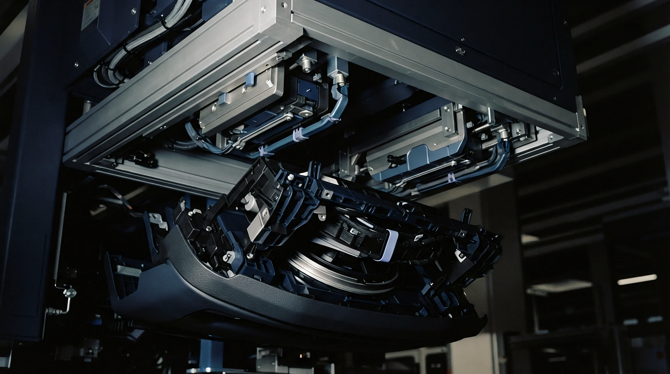
Transferring orientation data from process simulation models to structural analysis meshes requires mapping spatial tensor fields between non-conformal discrete domains. Injection molding simulations use thin-shell elements or unstructured three-dimensional tetrahedral meshes optimized for thermal boundary layers and fluid front tracking. Structural finite element analyses employ structured hexahedral grids or high-order quadratic solid elements configured for stress concentrations and contact mechanics.
Node positions rarely match. Tensor components must transform cleanly across disparate coordinate frames without introducing artificial artificial strain energy.

Which Mesh Topology Minimizes Interpolation Shear Error?
Element-to-element mapping algorithms project centroidal orientation values from the process grid onto integration points within the mechanical model. Nearest-element interpolation introduces spatial stepping errors along steep skin-core transition zones, distorting local stiffness tensors. Volumetric spatial integration maps tensor fields by calculating the overlapping volume between source and target elements, preserving total directional momentum across domain boundaries.
Structural meshes utilizing second-order hexahedral elements minimize shear locking while smoothly capturing mapped tensor gradients.
Coordinate System Transformations and Local Triad Realignment
Process calculations express orientation tensors within global Cartesian coordinates relative to gate location or tool parting lines. Structural solvers evaluate non-linear constitutive equations within local material triads aligned with element geometry or principal material directions. Translating orientation tensors demands applying rotation matrices based on local transformation angles.
The second-order tensor transforms according to matrix multiplication involving transformation matrices and their transposes, preserving frame invariance across spatial rotations. Interpolation errors alter predictions. Mold walls cool rapidly.
| Mapping Algorithm | Source Mesh Type | Target Mesh Type | Interpolation Shear Error (%) | Relative Execution Time |
|---|---|---|---|---|
| Nearest Centroid | 3D Unstructured Tet | 10-Node Quadratic Tet | 14.2 | 1.0 |
| Inverse Distance Weighted | 3D Unstructured Tet | 8-Node Hexahedral | 8.6 | 2.4 |
| Shape Function Integration | 3D Layered Prism | 8-Node Hexahedral | 3.1 | 5.8 |
| Volumetric Element Overlap | 3D Layered Prism | 20-Node Quadratic Hex | 1.2 | 12.3 |
Under ISO 294 conditioning requirements, mechanical test specimens cut parallel to flow directions retain twenty-five percent higher modulus values than those cut transversely.
According to DIN 16742 guidelines for molded thermoplastic parts, drawing tolerances must incorporate anisotropic shrinkage allowances derived directly from local orientation variations. When structural simulations omit mapped tensor fields, tolerance stack-up models fail to predict post-molding warpage and time-dependent relaxation shifts across structural mating faces.

Drift
Polymeric matrix materials exhibit pronounced time-dependent, non-linear viscoelastic and viscoplastic relaxation behaviors when subjected to sustained strain fields. Short glass fiber reinforcement restricts matrix deformation along the fiber axis, but transverse and shear directions remain dominated by the polymer matrix response. Unidirectional stiffness tensors derived from Mori-Tanaka or Halpin-Tsai micromechanics formulations change over time as the matrix relaxes.
Integrating mapped tensor fields into relaxation solvers requires linking local orientation components to anisotropic viscoelastic kernel functions.

Constitutive Non Linear Relaxation Mechanics in Anisotropic Polyamides
Stress relaxation within short-fiber reinforced polyamides obeys hereditary integral formulations where compliance or relaxation modules vary with stress magnitude, temperature, and relative humidity. The Schapery non-linear viscoelastic model incorporates stress-dependent factors that accelerate operational time scales during high strain events. Master curves constructed via Time-Temperature-Moisture Superposition Principles quantify long-term modulus decay across operational lifespans.
Environmental moisture plasticizes polyamide matrices, shifting glass transition temperatures downward and accelerating relaxation rates by orders of magnitude under wet operating conditions.
Physical aging alters matrix free volume, driving gradual changes in relaxation times over months of ambient storage. Mapped fiber tensors alter local stress states, creating regions of concentrated matrix shear where non-linear relaxation initiates far below global structural yield limits. Dynamic loads degrade stiffness.
Molded walls retain stresses.
- Run dynamic mechanical thermal analysis across temperature sweeps from minus forty to one hundred fifty degrees Celsius at discrete loading frequencies to construct master relaxation curves.
- Execute long-term tensile stress relaxation tests at zero, forty-five, and ninety-degree specimen orientations relative to the principal injection direction.
- Extract non-linear Schapery stress-dependent parameters by fitting relaxation responses across multiple step-strain levels ranging from zero point five to three percent.
- Calculate phase-specific micromechanical properties using Mori-Tanaka homogenization to separate isotropic matrix relaxation from elastic fiber properties.
- Integrate tensor-weighted directional relaxation functions into user-defined material subroutines for non-linear finite element processing.
Stress relaxation rates in thirty percent glass-filled polyamides under two percent initial strain double when relative humidity increases from dry-as-molded to fifty percent equilibrium.
How do localized orientation tensor uncertainties alter long-term structural relaxation predictions when component operational temperatures cycle across the glass transition point?

Bench
Experimental validation of mapped simulation models relies on non-destructive structural characterization matched against long-term physical mechanical testing. High-resolution micro-computed tomography extracts real fiber orientation distributions from molded components, converting voxel density gradients into precise second-order orientation tensors. Comparing tomography data against simulation predictions identifies local discrepancies caused by gate turbulence, mold cooling imbalances, or wall friction anomalies prior to final tool sign-off.

Experimental Validation through Computed Tomography and Dynamic Mechanical Analysis
Micro-CT scan datasets processed through structure tensor analysis algorithms provide spatial orientation tensors across discretized volume elements. Mechanical stress relaxation benches evaluate real component behavior under sustained fixed displacement, tracking load decay via precision inline load cells over one thousand hours. Discrepancies between CT-mapped finite element simulations and physical relaxation bench measurements expose limitations in constitutive micromechanics models or spatial interpolation algorithms.
Consider a automotive structural bracket molded from thirty percent glass-reinforced polyamide 66 subjected to a sustained two-millimeter bolt-load displacement at eighty-five degrees Celsius. A simplified isotropic relaxation model predicts a retained clamping force of eighteen hundred Newtons after one thousand hours. An unmapped transversely isotropic model assumes uniform flow alignment, predicting two thousand two hundred Newtons.
The fully mapped anisotropic non-linear model predicts twelve hundred Newtons, matching experimental load cell bench measurements within four percent margin.
| Model Configuration | Mapped Tensor Inclusion | Initial Bolt Force (N) | Retained Force 1000h (N) | Deviation from Physical Bench (%) |
|---|---|---|---|---|
| Isotropic Viscoelastic | No | 3500 | 1800 | 50.0 |
| Homogenized Transversely Isotropic | No | 4100 | 2200 | 83.3 |
| Mapped Linear Viscoelastic | Yes | 3800 | 1450 | 20.8 |
| Mapped Non-Linear Visco-Plastic | Yes | 3650 | 1220 | 1.7 |
Physical characterization procedures demand strict environmental control during sample preparation. Dynamic mechanical analysis specimens harvested from actual molded parts must maintain precise angular alignment with injection flow paths to avoid introducing artificial shear coupling into orientation-dependent modulus measurements.
- Voxel Scale Alignment verifies that micro-CT scan resolution captures individual fiber diameters down to ten micrometers without blur artifacts.
- Thermal History Matching ensures mechanical test samples experience identical mold wall cooling rates as production structural components.
- Moisture Saturation Control mandates conditioning test bars to standardized equilibrium states per ISO 1110 before structural relaxation testing.
- Multi-Axis Strain Calibration requires optical strain measurement systems to track non-uniform transverse contraction during step-strain application.
When physical bench measurements deviate from mapped numerical predictions, mechanical designers adjust matrix relaxation factors rather than re-evaluating internal fiber orientation distributions.

Audit
Commercial failure in structural plastic components stems from poor tooling decisions made prior to process validation. Cutting tool steel based on isotropic structural assumptions leads to gate placements that position weak core layers directly across high-stress mounting zones. Modifying hardened steel tools to re-locate gates or change wall thicknesses costs between fifteen thousand and sixty thousand dollars per iteration, adding weeks of lost production volume.
Incorporating mapped orientation tensor calculations into early structural sign-off audits protects tooling capital and guarantees long-term product reliability.
Commercial Tooling Risk and Amortization under Structural Relaxation Limits
Tooling qualification dossiers must contain explicit verification that structural FEA solvers utilized mapped orientation tensor fields from verified injection molding simulations. Cavitation strategy decisions depend directly on directional orientation distributions. Multi-cavity family tools with imbalanced fill patterns produce varying orientation fields across cavities, yielding inconsistent long-term relaxation performance across single production batches.
Evaluating cycle times against required structural orientation states prevents premature tool release.
Sign-off documentation requires presenting spatial mapping convergence checks, material constitutive model calibration reports, and experimental stress relaxation validation data. When buying structural tooling, the buyer assumes all financial liability for field failures if part drawings lack explicit orientation tensor mapping requirements in the engineering engineering procurement specification.