Correlating Sub Gate Volumetric Void Volume Drift with Multi Cavity Tool Amortisation Cycles
Sub gate wear enlarges gate cross-sections, dropping cavity pack pressure and driving core void growth; replacing gate inserts preserves amortisation schedules.


Wear

Submarine Gate Orifice Erosion Dynamics
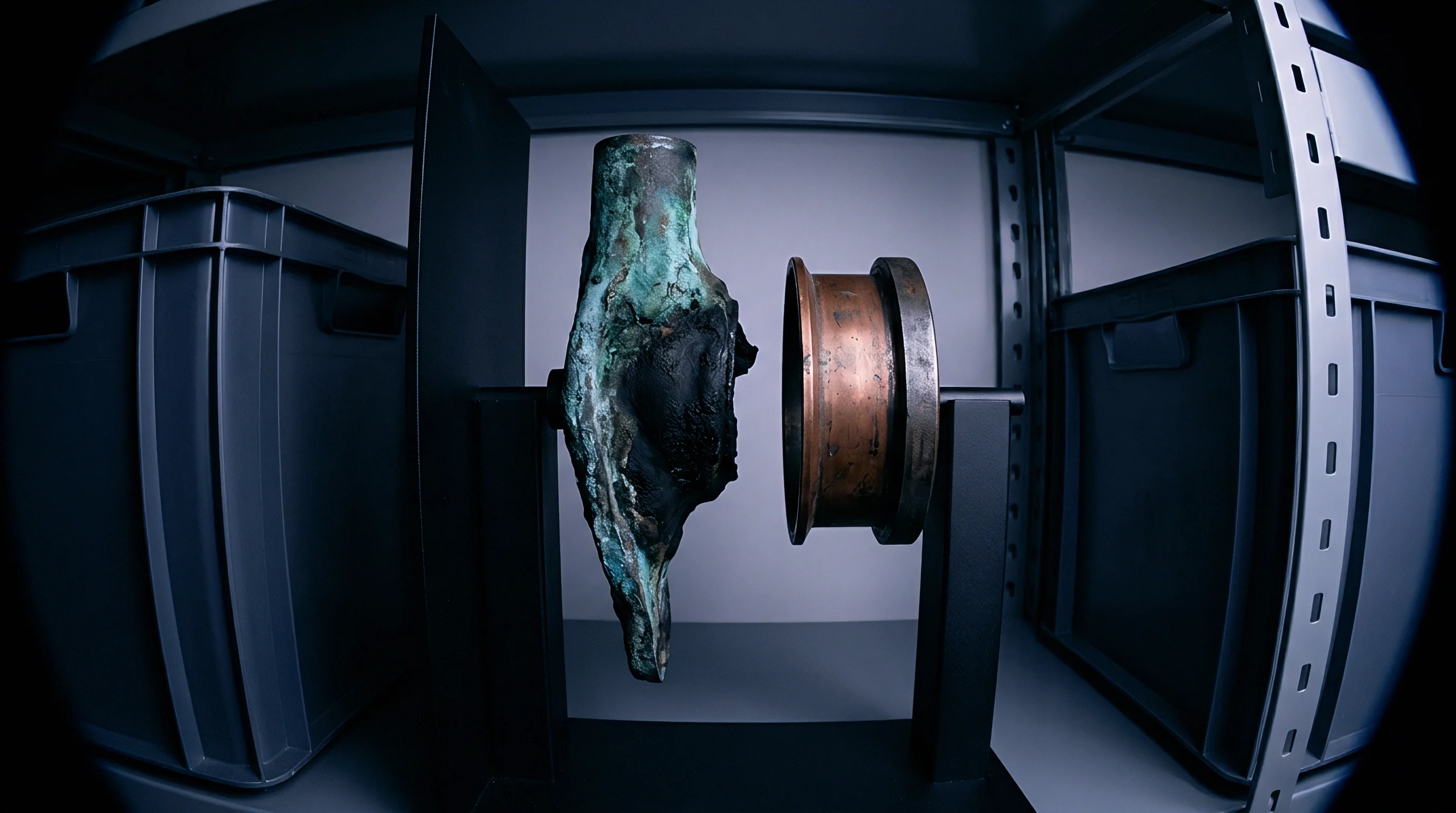
Polymer melt driven through a restrictive tunnel entry at velocities exceeding fifty meters per second generates localized shear stress that strips steel molecules from cavity inserts. Glass fibers oriented along the flow vector act as micro-abrasives against hardened tool steel, enlarging the cross-sectional area of sub gates over high shot counts. Standard round or banana sub gate geometries experience non-uniform erosion concentrated at the sharp land boundary where the runner splits into the mold cavity.
As the effective gate diameter expands from an initial decimal specification of 0.80 millimeters to 1.15 millimeters across several hundred thousand cycles, the local pressure drop across the gate orifice degrades significantly.
Steel yields to friction. The reduction in pressure drop alters the shear heating imparted to the resin during the injection phase. Lower local shear heating elevates the effective viscosity of the polymer entering the cavity, changing the fill pattern and thermal history of the part core.
When processing semi-crystalline polymers such as thirty-percent glass-filled polyamide, this viscosity drift restricts the packing phase. The frozen layer at the gate forms prematurely relative to the enlarged cross-section, isolating the interior volumetric volume of the part before pack pressure can compensate for volumetric thermal shrinkage.
Volumetric thermal shrinkage exceeding four percent in unpacked core sections generates internal vacuum voids directly downstream of eroded sub gates.
Internal void formation manifests as structural weakness without presenting visible defects on the exterior cosmetic surface of the molding. Micro-computed tomography demonstrates that internal void volume expands exponentially once gate erosion crosses a critical geometric threshold. Initial stage wear increases gate volume while maintaining acceptable part density, but secondary wear opens the gate land length, disrupting the freeze timing required for scientific moulding pack profiles.
The internal void acts as a stress concentrator during mechanical loading, resulting in premature tensile failure under operational loads.
Engineers tracking tool health must monitor the physical manifestations of orifice degradation before part failure occurs in service. The following failure mechanisms directly trace their origin to sub gate erosion in multi-cavity tooling:
- Core Void Expansion occurs when thermal contraction pulls the liquid polymer core toward the frozen outer walls after premature gate freeze isolates the cavity.
- Sink Mark Emergence appears on thick wall sections adjacent to the gate region when packing pressure falls below the threshold needed to maintain surface wall contact during cooling.
- Weld Line Displacement results from shifts in melt front velocity across asymmetric gate openings, relocating mechanical weld zones away from targeted structural rib intersections.
- Part Weight Decay develops systematically across production runs as reduced core density lowers total shot weight despite constant cushion positions on the press.
Unchecked gate orifice growth leads directly to structural part rejection at final assembly, forcing expensive emergency tooling overhauls that halt active production lines.


Pressure
Decay Profiles across Extended Run Cycles
Continuous monitoring of peak cavity pressure provides an early warning signal for geometric gate degradation long before dimensional inspection flags out-of-spec parts. Piezoelectric quartz sensors installed directly behind ejector pins in the gate region record the instantaneous transfer of hydraulic pressure into structural cavity force. During early tool life, the pressure trace exhibits a sharp packing spike followed by a clean, sustained hold phase.
As the sub gate erodes, hydraulic force transmission efficiency decays due to altered melt viscosity and altered shear history across the gate land.
Void volumes expand quietly. Process control charts often show stable hydraulic system pressures while actual cavity pressure peaks decline by twelve to fifteen percent over five hundred thousand injection cycles. The press operator observes a fixed cushion volume and identical screw position profiles, concealing the loss of effective packing inside the mold cavity.
Pycnometry testing of sectioned parts confirms a direct correlation between this hidden cavity pressure loss and an increase in internal volumetric void percentage.
| Cycle Count | Gate Area Increase (%) | Peak Cavity Pressure (bar) | Hold Pressure Loss (%) | Mean Void Volume (%) |
|---|---|---|---|---|
| 10,000 | 0.0 | 650 | 0.0 | 0.12 |
| 250,000 | 4.2 | 635 | 2.3 | 0.28 |
| 500,000 | 11.8 | 590 | 9.2 | 0.85 |
| 750,000 | 22.5 | 540 | 16.9 | 1.94 |
| 1,000,000 | 38.1 | 475 | 26.9 | 3.82 |
Data recorded under controlled conditions using ISO 294 standard test specimens confirms that internal void drift accelerates rapidly once gate area expansion exceeds fifteen percent. The primary driver of this acceleration is the loss of effective hold time. Larger gate cross-sections with eroded land lengths cool unpredictably, creating thermal gradients that cause the gate to seal prematurely or remain open long enough to allow backflow into the runner system.
Process parameters specified under ISO 294 force tight control on melt temperature and cavity pressure to prevent internal void growth in structural specimens.
Machine technicians frequently attempt to counter internal void formation by increasing pack pressure or extending hold times on the press interface. Paraphrasing common tooling shop responses, suppliers often claim that minor void growth is easily corrected by adding two seconds of hold time or raising hydraulic boost pressure by ten bar. This operational patch masks the underlying mechanical wear of the hardened steel gate inserts, elevating internal stress in the part while failing to restore original core density.


Variance

Multi Cavity Imbalance and Thermal Asymmetry
Tooling layouts featuring sixteen or thirty-two cavities rarely experience uniform sub gate wear across all positions simultaneously. Minor variations in melt delivery temperature through hot runner nozzles create non-uniform shear profiles, causing inner cavities to wear faster than outer cavities. Natural flow imbalance concentrates higher shear rates in central manifold paths, eroding those specific sub gates at nearly double the rate of perimeter cavities.
Over extended production cycles, this localized wear splits the tool into two distinct processing populations.
Density drops inside core zones. The inner cavities develop larger gate orifice areas, higher volumetric void growth, and reduced part weights, while the outer cavities maintain baseline physical properties within drawing limits. Dimensional inspection under DIN 16742 Class TG4 reveals that structural tolerances drift out of compliance in central cavities long before outer cavities reach end-of-life criteria.
Quality control sampling that mixes parts from all cavities hides this variance within statistical averages, allowing defective parts to pass inspection lots.
To identify and isolate cavitation imbalance before whole-tool scrap occurs, quality engineers execute a structured qualification audit across the tool base:
- Isolate Cavity Streams by collecting fifty consecutive shots and segregating parts into individual cavity bins for detailed weight and dimensional tracking.
- Conduct Micro-CT Scanning on parts sampled from high-wear center positions and low-wear perimeter positions to map exact internal void locations and calculate void volume percentages.
- Measure Gate Shear Profiles using inline pressure transducers to construct pressure drop curves across each runner branch under identical press settings.
- Perform Optical Metallography on removable sub gate steel inserts to verify physical wear patterns, measuring gate land length and orifice eccentricity against original CAD geometry.
- Establish Cavity Scrap Cutoffs by setting maximum allowable void volume limits per cavity stream, locking out individual hot runner nozzles when wear thresholds are exceeded.
Evaluating multi-cavity tool drift requires understanding the complex interaction between mechanical wear, thermal distribution, and rheological flow asymmetry across the runner block.

How Does Cavity Location Accelerate Sub Gate Erosion?
Hot runner thermal distribution creates localized viscosity drops in central manifold channels, driving higher volumetric flow rates through the corresponding sub gates. Higher volumetric flow increases shear stress against the tool steel, accelerating mechanical erosion in center cavities relative to colder perimeter positions. This thermal and mechanical loop continuously widens the volumetric void volume gap between cavity positions as total tool cycles accumulate.
Unbalanced gate erosion degrades process capability across long manufacturing runs. When inner cavities produce two percent void volumes while outer cavities hold zero point two percent, no single press setting can yield acceptable parts from all cavities simultaneously. Adjusting process settings to fix inner cavity voids causes flashing or high residual stress in outer cavities.
The section leaves open the question of whether predictive shear modeling during mold design can completely eliminate unequal gate erosion patterns in multi-cavity tooling running abrasive resins.


Amortisation
Tooling Lifetime Capital Payoff Mechanics
Tooling capital budgets rely on precise piece-price allocations that amortize initial mold manufacturing costs over a target number of acceptable production parts. When sub gate void volume drift forces early cavity shut-offs or premature tool maintenance, the financial calculation supporting the landed piece price breaks down. A thirty-two cavity tool designed to amortize five hundred thousand dollars over three million shots must maintain all thirty-two cavities in active, compliant service to hit target unit costs.
Scrap rates escalate rapidly. If eight inner cavities are disabled at cycle seven hundred fifty thousand due to excessive volumetric void drift, the remaining twenty-four cavities must absorb the remaining capital depreciation cost. This reduces production output per press hour by twenty-five percent while increasing the tool amortization burden per good part from sixteen point six cents to twenty-two point two cents.
The financial impact compounds when press time costs are included, as machine-hour rates of one hundred twenty dollars per hour are distributed over fewer good parts per cycle.
Consider a practical cost analysis for a high-volume component moulded in PA66-GF30 on a 16-cavity tool amortized over 1,500,000 cycles with an initial tool capital expenditure of $240,000:
- Initial Amortization Rate equals $0.0100 per part based on 24,000,000 total theoretical parts (16 cavities times 1,500,000 cycles).
- Accelerated Wear Trigger occurs at 600,000 cycles, expanding sub gate orifices in 4 central cavities beyond acceptable void thresholds (void volume > 1.5%).
- Scenario A (Run to Failure with Disabled Cavities) shuts off 4 cavities; remaining 12 cavities run from cycle 600,000 to 1,500,000, producing 10,800,000 parts. Total production drops to 20,400,000 good parts, increasing amortized tooling cost to $0.0118 per part, plus a press downtime loss calculated at $48,000 across the tool life.
- Scenario B (Planned Sub Gate Insert Refurbishment) replaces modular carbide sub gate inserts at cycle 600,000 at a total tooling service cost of $14,000 including downtime, restoring all 16 cavities to baseline condition for the remainder of the amortisation life.
| Financial Metric | Baseline (Zero Wear) | Scenario A (Disable Cavities) | Scenario B (Refurbish Inserts) |
|---|---|---|---|
| Active Cavities (Cycles 600k-1.5M) | 16 | 12 | 16 |
| Total Compliant Parts Delivered | 24,000,000 | 20,400,000 | 24,000,000 |
| Effective Tooling Cost per Part | $0.0100 | $0.0118 | $0.0106 |
| Total Press Hour Overhead Cost | $180,000 | $228,000 | $180,000 |
| Net Financial Impact vs Baseline | $0 | +$84,720 (Loss) | +$14,400 (Cost) |
The calculation proves that proactive maintenance of sub gate regions yields a significant financial advantage over running damaged tools with shut-off cavities. Installing modular sub gate inserts made from micro-grain tungsten carbide extends the wear life before initial void drift appears, shifting the refurbishment threshold further down the amortisation curve.
Replacing wear-prone sub gate steel with carbide inserts before initial tool qualification protects capital payoff schedules across multi-million shot production contracts.
Tooling budgets absorb wear. Operating high-cavitation tooling without defined gate refurbishment milestones guarantees piece-price erosion as internal void defects drive up scrap rates and press hour losses over time.

Contract
Quality Verification and Sourcing Provisions
Sourcing agreements for high-precision injection molded components must explicitly define sub gate wear limits, volumetric void thresholds, and maintenance cost responsibilities before tool construction begins. Generic commercial agreements covering dimensional compliance under ISO 2768 or DIN 16742 often fail to address non-visible internal void drift, leaving buyers unprotected when parts fail structural testing despite matching exterior drawing dimensions. The Master Supply Agreement must specify non-destructive testing protocols and maximum allowable internal void volumes as binding quality metrics.
Gate inserts require replacement. Procurement contracts should establish clear rules governing tool ownership, maintenance reserves, and insert replacement triggers based on measurable process performance indicators rather than arbitrary cycle thresholds. The table below outlines mandatory contract documentation required to protect both buyer and supplier throughout the tool amortisation lifecycle:
- Sub Gate Geometry Specifications establishing maximum allowed gate land length growth and cross-sectional area expansion limits before insert refurbishment is mandated.
- Volumetric Void Limits defining maximum allowable internal core void percentage measured via micro-CT or pycnometric density testing under specified sampling frequencies.
- Cavity Imbalance Clauses stipulating maximum permissible part weight and cavity pressure variance between individual cavities within a multi-cavity tool base.
- Maintenance Reserve Allocations detailing the precise piece-price surcharge dedicated to tooling refurbishment and assigning financial responsibility for sub gate insert replacement.
Definite quality clauses prevent disputes when sub gate erosion compromises part integrity mid-way through a multi-year production program. Incorporating explicit technical benchmarks into purchasing documentation converts subjective maintenance arguments into clear, enforceable engineering criteria.
A standard quality assurance clause in supply contracts states: “The supplier shall perform non-destructive micro-CT scanning or density testing every fifty thousand cycles; internal volumetric void volume exceeding one point five percent in any cavity stream triggers mandatory tool insert replacement at the supplier’s expense under the agreed preventive maintenance schedule.”