Coordinate Measuring Machine Restraint Fixture Calibration for Thermoplastic Assemblies
Calibrate CMM restraint fixtures by matching datum locators to nominal CAD and regulating clamping forces to eliminate non-rigid part deflection.


Nest

Datum Simulation for Non-Rigid Parts
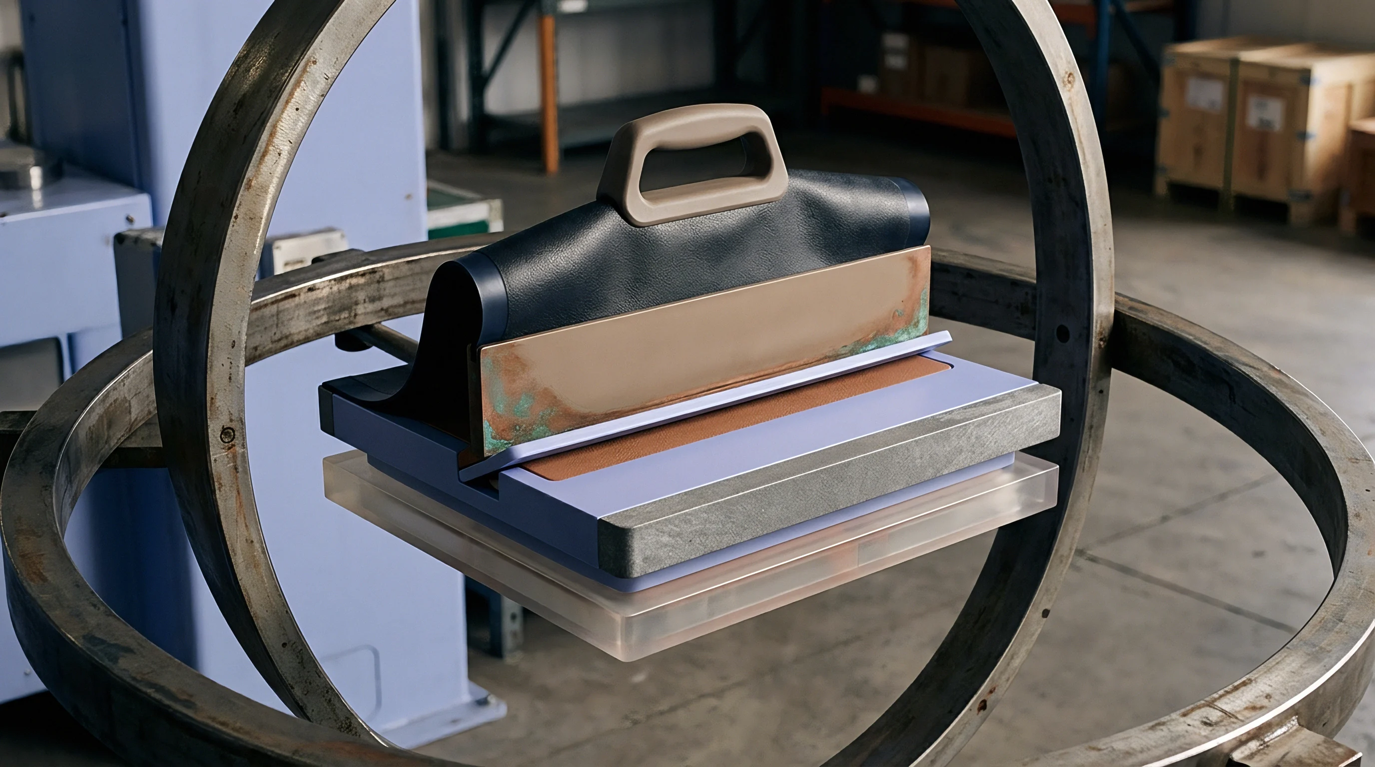
Holding a compliant injection-moulded component requires mechanical restraint that mirrors its installed state rather than forcing it flat. Residual cooling stresses, anisotropic shrinkage, and structural flexibility make these mouldings behave very differently on a coordinate measuring machine than rigid metal parts. Under ISO 10579 and ASME Y14.5 non-rigid part rules, inspection drawings frequently call out a restrained state, establishing fixed target locations and specific clamping forces.
The receiver block matches the nominal CAD surface only at discrete datum pads, which keeps thin-walled perimeter warp from triggering false out-of-tolerance flags during tactile or optical inspection.
Receiver nests are typically milled from hard-anodized 6061-T6 aluminium, tool steel, or dense tooling polyurethane. Primary locators set the spatial plane through coplanar pads or three-point target areas. Secondary and tertiary datums rely on hardened pins fitted into moulded holes, slots, or molded rib features.
Diamond pins control rotation around the primary axis without binding under thermal growth or natural cavity-to-cavity shrinkage variation. Tooling standards routinely hold these datum pins within 0.005 mm to 0.012 mm of true position relative to the base grid.
Under ISO 10579 restraint specifications, drawing notes omitting clamp force values render dimensional inspection reports legally unenforceable during supplier quality disputes.

Locator Geometry Configuration
Fixtures rely on distinct pin and pad configurations to seat flexible thermoplastic parts repeatably:
- Full cylindrical locating pins establish two-axis spatial positioning on primary datum holes with ground diameters held to plus zero and minus five micrometres.
- Relieved diamond locating pins prevent binding along the long pitch axis of elongated thermoplastic slots while constraining orthogonal orientation.
- Segmented net support pads provide rigid backing against normal clamping vectors directly opposite external pneumatic or manual toggles.
- Scribe-line alignment blocks facilitate rapid visual cross-checks of split lines, parting lines, and peripheral perimeter witness marks before probe contact.
A sound locator layout isolates fixture restraint from standard part variation. If pin-to-hole clearance is too tight, operators end up forcing the part home, introducing plastic strain before the probe touches a surface. A diametrical pin clearance of 0.020 mm to 0.050 mm absorbs normal lot-to-lot shrinkage swings while preserving positional repeatability.
For structural mouldings under DIN 16742 tolerance group TG6, fixture locators cannot consume more than one-tenth of the part’s total tolerance band.
Drawings governed by ISO 10579 restraint callouts require the supplier to build and qualify duplicate CMM holding fixtures to identical datum coordinates before production tooling sign-off proceeds.
Deflection
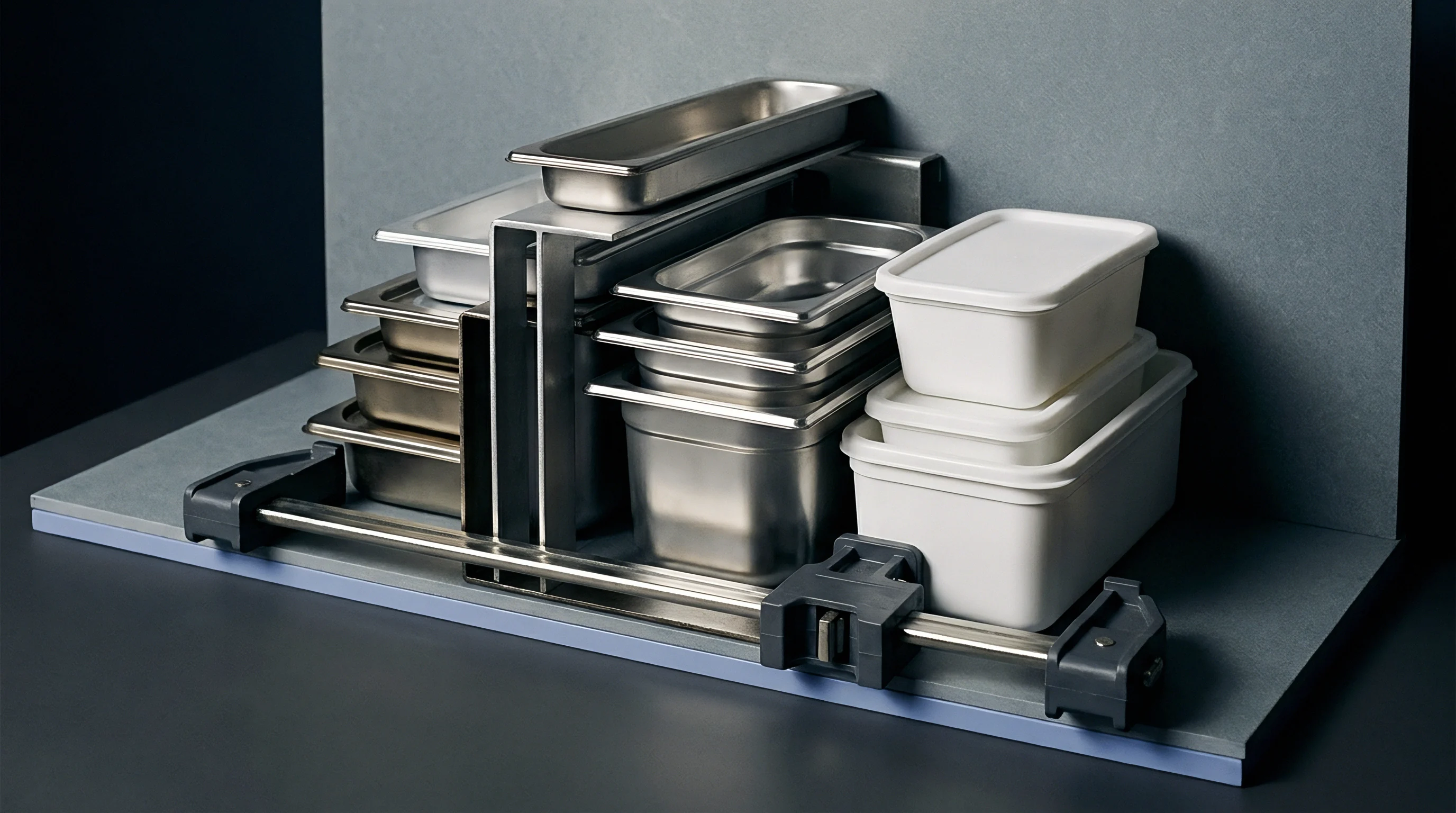
Why Do Clamping Sequences Alter Free State Profiles?
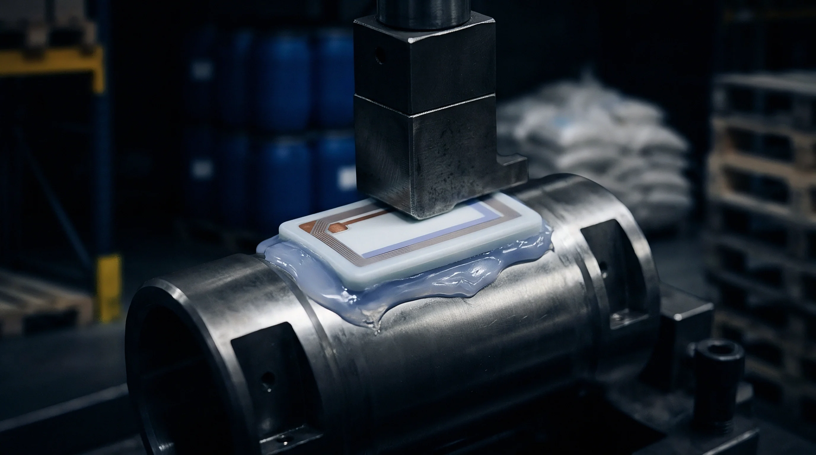
Under localized point loads, flexible mouldings behave like thin elastic shells. Locking down an outer corner toggle before seating the central datum pulls twist and bow straight through the unsupported spans. That sequence locks internal moulding stresses into flexural moments, throwing off coordinate measurements across adjacent features.
Repeatable CMM routines therefore rely on a strict clamping order: primary datum targets must be fully seated before lateral clamps make contact.
Clamping force has to secure the part without distorting it. Standard pneumatic cylinders and manual toggle clamps easily exert enough force to exceed the yield point of unfilled polypropylene, ABS, and polyoxymethylene. Too much pressure crushes structural micro-ribs, thins local wall sections, and kicks opposing free edges off nominal coordinates.
Calibrated spring plungers, vacuum channels, and simple deadweight blocks steady the component without locking in mechanical preload.
| Polymer Chemistry | Tensile Modulus (MPa) | Clamp Pressure Limit (MPa) | Tactile Probe Force (N) | Local Displacement (mm) |
|---|---|---|---|---|
| Polypropylene Unfilled | 1300 to 1500 | 0.35 | 0.08 to 0.12 | 0.014 to 0.022 |
| ABS General Purpose | 2100 to 2400 | 0.60 | 0.10 to 0.15 | 0.008 to 0.012 |
| PA66 30% Glass Filled | 8000 to 9500 | 1.80 | 0.20 to 0.30 | 0.002 to 0.004 |
| PBT 20% Glass Filled | 6500 to 7500 | 1.40 | 0.15 to 0.25 | 0.003 to 0.006 |
| Polycarbonate Optical Grade | 2300 to 2500 | 0.75 | 0.10 to 0.15 | 0.007 to 0.011 |
Sequential Clamping Protocol Execution
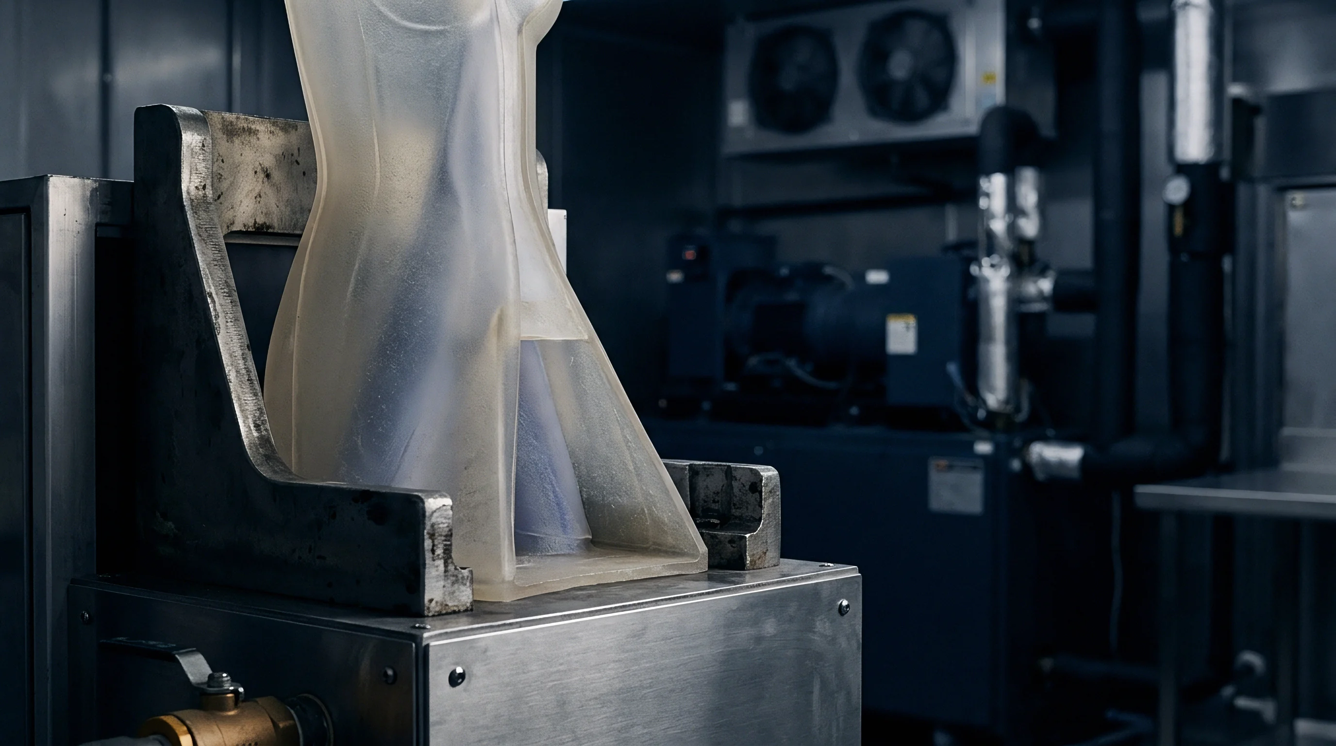
Loading compliant parts into an approved CMM nest follows an explicit order to avoid inducing mechanical strain:
- Primary datum pad alignment involves placing the component manually onto polished receiver surfaces without applying lateral constraint.
- Gravity settling verification ensures unobstructed contact across three baseline coordinates prior to external tool engagement.
- Secondary locator pin engagement introduces lateral diamond and round pin guidance through low-friction axial guides.
- Primary toggle application drives the part against normal datum planes using calibrated pneumatic cylinders limited to specified pressure ceilings.
- Perimeter holding clamp activation secures outer flanges and free spans using constant-force spring clips.
An improper clamping sequence creates phantom dimensional errors that turn into protracted disputes between moulders and assembly plants. Probe trigger force creates a similar problem. Standard tactile styli exert 0.05 N to 0.30 N at contact.
On a 1.5 mm unfilled polypropylene skin, a 0.20 N trigger force produces up to 0.018 mm of local elastic deflection under the ruby tip, burying the true surface profile beneath contact flexure.
The unresolved question remains whether high-speed optical scanning with zero tactile force can fully supersede mechanical contact fixtures across non-rigid thermoplastic parts exhibiting intense internal moulding stresses.

Torque

Where Does Contact Force Induce Plastic Creep?
Sustained clamp pressure triggers time-dependent viscoelastic creep in amorphous and semi-crystalline resins alike. Held under continuous clamp load, polymers undergo molecular relaxation, shifting measurably over extended CMM routines. On complex mouldings like automotive door cards or instrument clusters, where tactile routines often take twenty to forty minutes, clamp contact points migrate.
Adding torque limiters to manual screw clamps keeps preload consistent and prevents operators from over-torquing the fixture.
Uncontrolled manual toggles invite substantial process scatter. Clamping forces vary from 20 N to over 150 N depending on operator hand strength and shift fatigue. Using calibrated torque thumbscrews or miniature load cells keeps holding forces inside a narrow, repeatable band.
Miniature strain-gauge cells embedded straight into the nest allow quick verification of clamp loads during routine gauge audits.
Calibrating manual screw clamps to 0.45 Nm torque limits local component thinning to less than 0.003 mm across thirty-minute inspection cycles.

Clamp Calibration Instrumentation
Metrology technicians use specialized instruments to certify fixture holding mechanics and load parameters:
- Miniature compression load cells measure dynamic clamping force directly between the toggle clamp pad and receiver nest.
- Digital torque screwdrivers certify manual clamp screw threads, ensuring consistent preload values across all fixture positions.
- Linear displacement dial indicators track part deflection during clamp engagement to detect localized structural oil-canning.
- Pressure transducers regulate pneumatic supply lines feeding automated actuator cylinders on high-volume production fixtures.
Routine maintenance requires tracking clamp load retention over time. As pneumatic seals harden and toggle linkages wear, holding pressure drops off, allowing parts to flutter or lift during high-acceleration probe transitions. Re-calibrating pneumatic regulators every quarter guarantees that applied forces remain within five percent of the engineering specification.
Clamp force must seat the substrate firmly against locator pads without generating permanent plastic deformation or localized oil-canning across unsupported spans.

Compliance

Measurement System Analysis on Restrained Assemblies
Evaluating fixture capability requires rigorous Gauge Repeatability and Reproducibility studies under dynamic loading conditions. Traditional Gauge R&R protocols evaluate total measurement system variation, isolating operator error from equipment instability. In flexible thermoplastic inspection, part loading, fixture clamping repeatability, and thermal relaxation represent significant portions of total process variation.
Total Gauge R&R values exceeding ten percent of the tolerance band indicate unacceptable fixture compliance, requiring structural redesign or improved datum locating features.
Measurement stability depends directly on the rigidity of the fixture frame. Bases machined from thin plate flex visibly under the combined load of pneumatic cylinders and probe hits. Fixture tooling plates require minimum thicknesses of 35 mm to 50 mm, backed up by diagonal stiffening ribs.
Mounting the nest on kinematic balls or three-point ceramic pads isolates it from thermal movement in the CMM granite bed.
A rigid fixture base prevents mechanical deflection from consuming part tolerance bandwidth.

Wear Tracking and Dimensional Drift
Moulded thermoplastic polymers, particularly grades reinforced with abrasive short glass fibres or mineral fillers, induce severe sliding wear on locator pins and support nests. PA66-GF30 and PBT-GF20 act as grinding compounds against unprotected 6061-T6 aluminium surfaces. Hard chrome plating, titanium nitride coatings, or solid carbide locating inserts resist sliding abrasion across hundreds of thousands of production loading cycles.
Standard quality protocols call for three-axis CMM verification of the bare nest every six months. Laser tracking or contact probing checks datum pin wear, locator pad grooving, and guide bushing play back to the original CAD model. Wear exceeding 0.010 mm on primary locating elements mandates replacement of the tooling insert.
Deploying worn datum pins or uncalibrated clamping fixtures creates systematic measurement bias, resulting in false cavity acceptance and high downstream assembly line reject rates.
Allowance
Thermal Expansion Compensation across Dissimilar Materials
Thermal expansion differences between the fixture and the polymer part introduce substantial measurement bias when room temperatures drift. Unfilled polypropylene has a linear coefficient of thermal expansion around 150 times ten to the minus sixth per Kelvin, while 6061-T6 aluminium expands at 23 times ten to the minus sixth per Kelvin and tool steel at 11 times ten to the minus sixth per Kelvin. On a 1000 mm automotive bumper fascia or tailgate trim, a 4 degrees Celsius departure from the standard 20 degrees Celsius metrology baseline causes 0.60 mm of differential expansion between moulding and fixture.
Primary calibration labs regulate temperatures to 20 degrees Celsius plus or minus 1 degree Celsius. Press-side inspection rooms, however, often swing by 6 degrees Celsius across twenty-four hours, causing parts to bind hard against fixed pins. Fixture builders resolve this by slotting secondary datum holes and mounting locators on linear slides, allowing natural thermal expansion without inducing buckling stress.
| Material Pair | Part CTE (10⁻⁶/K) | Fixture CTE (10⁻⁶/K) | Expansion Mismatch over 500 mm at ΔT = 3 K (mm) | Required Pin Slide Clearance (mm) |
|---|---|---|---|---|
| PP Unfilled / Tool Steel | 150 | 11 | 0.208 | 0.250 |
| ABS Unfilled / Aluminium 6061 | 85 | 23 | 0.093 | 0.120 |
| PA66-GF30 / Aluminium 6061 | 35 | 23 | 0.018 | 0.030 |
| PC/ABS Blend / Tool Steel | 70 | 11 | 0.088 | 0.100 |
| POM Copolymer / Aluminium 6061 | 110 | 23 | 0.130 | 0.160 |
Compensating for thermal growth requires dynamic scaling inside the CMM metrology software. Modern packages run real-time scaling adjustments based on surface temperature readings taken just before the probe cycle starts. Environmental conditioning matters just as much.
Freshly moulded thermoplastic parts continue post-mould crystallization and volumetric shrinkage for twenty-four hours before reaching dimensional equilibrium.
Thermoplastic parts require twenty-four hours of thermal and crystalline soaking prior to dimensional qualification.

Uncertainty Budget Allocation
Calculating overall measurement uncertainty for restrained thermoplastic assemblies follows ISO 14253 guidelines. Fixture manufacturing tolerance, locator wear allowance, thermal mismatch compensation, tactile probe trigger uncertainty, and part flexural compliance combine in a root-sum-square calculation. The cumulative uncertainty must occupy less than twenty percent of the drawing tolerance band to maintain high process capability indices.
Engineering teams establish absolute tolerance allocations by auditing each physical contributor independently. The CMM volumetric repeatability contributes 0.003 mm, the calibrated fixture nest accounts for 0.008 mm, thermal drift contributes 0.015 mm, and local clamping flexure accounts for 0.012 mm. Combining these parameters yields an expanded measurement uncertainty of 0.021 mm at a ninety-five percent confidence interval, providing an accurate baseline for tooling wear compensation and injection moulding parameter adjustments.