Coordinate Measuring Machine Restraint Fixture Calibration Basics
Restraint fixture calibration certifies datum pad coordinates, pin locations, and clamp forces to isolate true part warpage from tooling fixture deflection.

Seat
Dimensional inspection of flexible injection mouldings begins at the contact boundary between the polymer skin and the metallic fixture base. Unrestrained mouldings twist freely. A glass-filled polyamide door inner or an unreinforced polypropylene fascia warps upon ejection from the tool cavity as differential shrinkage across uneven wall thicknesses generates residual stress.
Standard engineering drawings mark these parts with drawing notes under ISO 10579 or ASME Y14.38, specifying that inspection occurs in a restrained state where secondary clamping forces return the component to its nominal vehicle or assembly position. When an inspection fixture holds a part in this simulated position, the fixture itself functions as the functional physical datum reference frame for coordinate measuring machine probing. Calibration of this physical restraint apparatus establishes whether geometric rejections originate from actual tool steel discrepancies or from mechanical inaccuracies within the locating seats themselves.
Precision resting pads define the primary datum plane, neutralizing three degrees of spatial freedom through direct surface planar support. Steel tooling rejects deflection. Locating pins, usually configured as one full cylindrical diamond pin and one round four-way pin, establish secondary and tertiary datums by locating designated master tooling holes moulded into the component perimeter.
If these locators deviate from coordinate positions defined by computer aided design models, the coordinate measuring machine evaluates the part from a skewed reference matrix. A locating pad shifted by 0.05 mm translates into false deviations across the entire contour profile, prompting press technicians to adjust holding pressures or barrel temperatures to correct an error that does not exist in the polymer.
Calibration offsets on primary locating net pads directly displace the coordinate measuring machine spatial alignment matrix.
Restraint mechanisms counter the residual moulding bow without introducing artificial tensile or compressive deformation into the plastic. Clamping forces act perpendicular to the net pads to prevent local buckling or side slippage along the tooling surface. When toggle clamps or pneumatic pistons apply force off-axis relative to the resting pad centerline, the clamp induces local bending moments that flex the plastic shell away from adjacent reference points.
The metrology department must qualify the coplanarity and spatial coordinates of every resting pad in the fixture before qualifying any production moulding.

Datum Structure Calibration for Compliant Components
Physical reference blocks require absolute coordinate verification relative to the fixture base alignment bushings. Inspection fixtures incorporate three precision reference balls or dedicated bushed datum holes bored into the hardened aluminum or tooling-board sub-plate. An operator measures these base reference features on a calibrated bridge coordinate measuring machine to establish the fixture coordinate frame.
Probing routines subsequently survey the primary resting pads, assessing three-dimensional center points, surface flatness, and face angles against the nominal engineering model.
Tolerances for automotive and aerospace restraint fixtures typically permit no more than ten percent of the part tolerance band for fixture fabrication error. For an injection moulded interior trim panel carrying a profile tolerance of plus or minus 0.50 mm to datum reference frame ABC, the resting net pads demand true position limits within 0.05 mm and surface profiles within 0.02 mm of nominal CAD data. Pin diameters must hold cylindrical tolerances within plus 0.00 mm and minus 0.01 mm to eliminate mechanical play that would otherwise permit part float during automated touch probing.
| Fixture Element | Physical Function | Manufacturing Tolerance | Permissible Calibration Drift | Calibration Standard |
|---|---|---|---|---|
| Primary Net Pad | Arrests Z-axis translation and pitch/roll rotation | Profile 0.020 mm | 0.015 mm deviation | ISO 1101 Surface Profile |
| Round 4-Way Pin | Arrests X and Y translation | Diameter +0.000 / -0.010 mm | 0.008 mm total runout | ISO 286 Grade h6 |
| Diamond 2-Way Pin | Arrests yaw rotation around round pin | Width +0.000 / -0.012 mm | 0.010 mm position | ISO 286 Grade h6 |
| Base Reference Sphere | Establishes fixture origin for CMM alignment | Sphericity 0.002 mm | 0.003 mm diameter | DIN EN ISO 10360-2 |
| Mechanical Toggle Clamp | Applies clamping force opposing net pad | Alignment 0.100 mm to pad | 0.050 mm contact drift | VDI/VDE 2634 Part 2 |
Mechanical Alignment of Locating Pins and Nests
Hardened steel pins undergo severe side loads when technicians seat warped parts over tight clearances. Dial indicators detect runout. Over extended production campaigns, repetitive loading of high-shrinkage semicrystalline resins such as polybutylene terephthalate produces microscopic pin bending or loosening of the locator retaining bush.
Routine calibration cycles involve sweeping each pin shank with a sensitive dial test indicator or tactile coordinate measuring machine stylus to verify perpendicularity to the fixture baseplate.
Milled nests formed from aluminum or synthetic tooling boards support curved aesthetic class-A surfaces where discrete net pads would cause visible pressure marks. Coordinate verification across continuous sculpted surfaces demands dense surface scanning. A laser line scanner mounted on an articulated measuring arm or an optical photogrammetry rig captures millions of point coordinates across the nest contour, generating a color deviation map against the master CAD solid.
Surface deviation exceeding 0.03 mm requires toolmakers to spot-grind high spots or shim the supporting risers before the fixture returns to active quality surveillance duty.
- Interchangeable locator pins slide within precision hardened ground bushings to allow rapid replacement upon wear detection without remachining the base plate.
- Spring loaded sensor pins retract under excess part interference, signaling improper part seating before mechanical clamps lock the perimeter into place.
- Threaded riser shims adjust net pad heights in discrete ground increments during initial tool balancing without bending the underlying frame.
- Go and no-go check collars confirm pin engagement depth across stepped plastic datum bosses during manual part positioning before inspection runs begin.
Toolmakers routinely remark that an uncalibrated resting nest simply seats whatever geometry the injection press ejected, dismissing pin misalignment as harmless settle.


Traceability
Metrological chain of custody links shop-floor inspection nests directly to national length standards maintained by metrology institutes. Coordinate measuring machines used to certify restraint tooling undergo verification according to ISO 10360 series procedures using step gauges, calibrated ball bars, and laser interferometers. When a fixture leaves the toolroom for production receiving dock duty, its dimensional verification records establish legal proof of part conformity.
Without direct mechanical traceability linking fixture locators to calibrated measuring instruments, dimensional rejection reports collapse under contractual scrutiny during component assembly disputes.
Periodic calibration cycles depend on stable environmental control within the calibration room. Gauge blocks transfer traceability. Steel locating pins and cast aluminum fixture structures expand at different thermal rates during seasonal shop-floor temperature swings.
Standard laboratory conditions of 20 degrees Celsius with relative humidity below 50 percent prevent thermal distortion during fixture qualification. Measuring a fixture at 28 degrees Celsius on a plant floor produces thermal expansion errors that can consume forty percent of the permissible part tolerance envelope before probing touches a single plastic surface.
Optical Verification and Master CMM Artifacts
Laser trackers and high-resolution industrial photogrammetry systems offer rapid verification for massive multi-piece restraint bucks used in vehicle instrument panel and bumper fascias. Optical targets affixed directly to fixture datum pads allow technicians to verify dozens of spatial points without physical stylus deflection. Tactile coordinate measuring machines remain the governing referee tool for qualifying precision pin diameters, bushing true positions, and small net pad details.
Steel master artifacts, certified annually by accredited dimensional calibration laboratories under ISO/IEC 17025, qualify the volumetric accuracy of the coordinate measuring machine prior to any fixture survey.
Master golden parts formed from low-expansion carbon fiber composite materials or stabilized aluminum provide intermediate transfer standards. Technicians load the golden artifact into the restraint fixture at established monthly intervals to verify coordinate reproducibility. A deviation in the probed coordinates of the master artifact indicates mechanical drift in the fixture clamps or settling of the structural frame, triggering immediate withdrawal of the fixture from production acceptance workflows.
ISO 10579 dictates that nonrigid part drawing tolerances apply strictly in the restrained condition established by specified datum points and clamping parameters.
Calibration Workflows for Periodic Inspection
Maintaining fixture fidelity involves a systematic calibration workflow that verifies structural rigidity alongside surface coordinates. Fixture frames welded from hollow aluminum structural tubes or steel box sections experience internal stress relaxation over the first six months of factory service. Unrelieved internal stresses cause long-term twisting of the base plate, carrying locating pins out of mutual planar alignment.
- Visual structural inspection identifies loose mounting hardware, cracked dowel pin bosses, and score marks along datum pin shanks that impede smooth part loading.
- Coordinate frame zeroing verifies the spatial relationship among the three primary tooling spheres or master alignment bushings using calibrated tactile styli.
- Net pad profile sweep measures the Z-axis height and spatial orientation of every resting surface under continuous contact scanning to detect localized mechanical gouging.
- Locator pin runout survey evaluates roundness, diameter, and perpendicularity to the baseplate using multi-point circular probing routines at multiple height steps.
- Clamp alignment verification evaluates whether toggle clamp pressure tips land centered on their respective opposing net pads without angular skew.
Incorporating ISO 10579 Section 4 into the purchase specification shifts the legal presumption of conformity by establishing that measurements taken without recorded datum pin coordinates fail inspection before the part ever touches a coordinate measuring machine.

Force
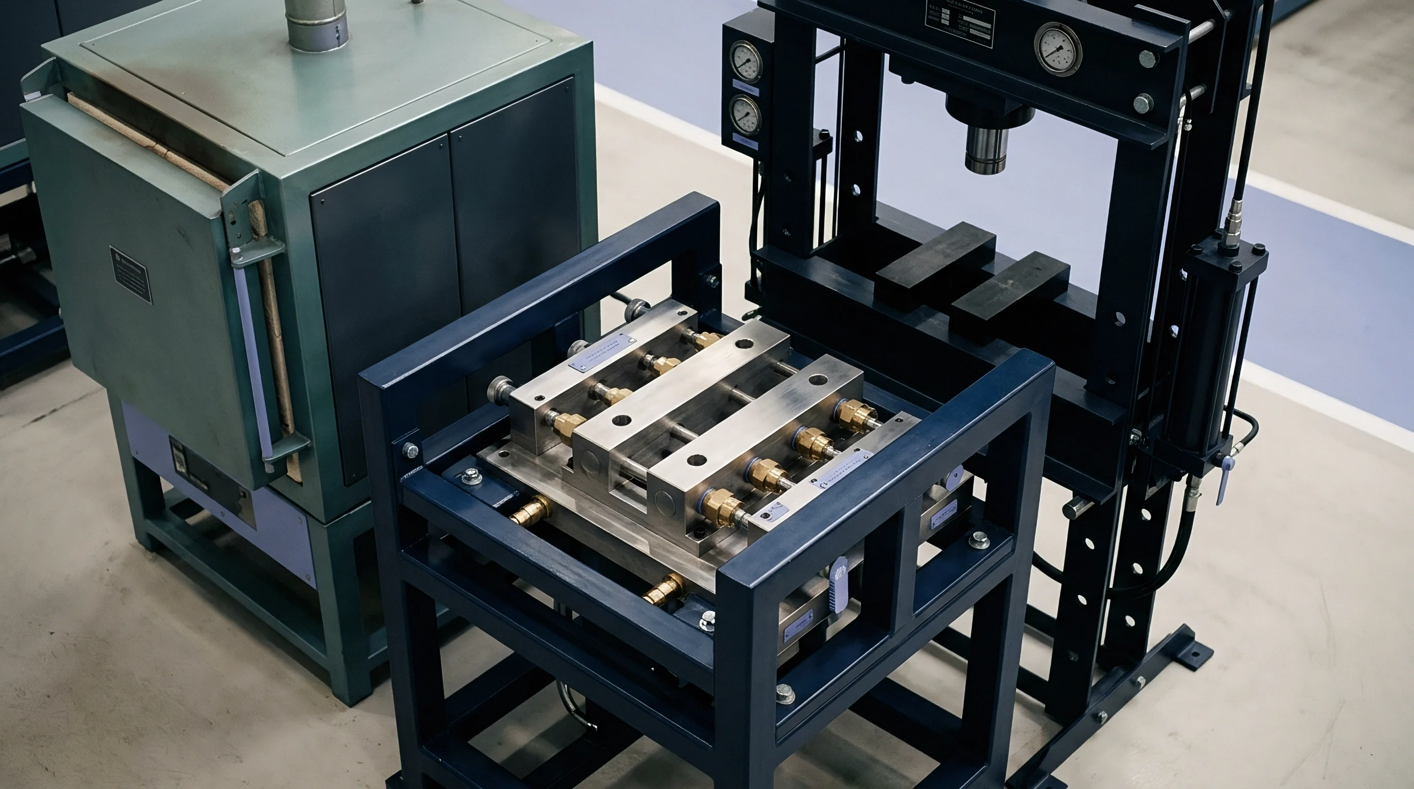
Mechanical clamping forces hold compliant plastic mouldings against reference pads to overcome free-state warpage. Clamps induce mechanical strain. In injection moulding of thin-walled parts, injection pack pressure and cooling gradient variations generate internal residual stress profiles.
Parts released from the mould show out-of-roundness or saddle warpage. Restraint fixtures simulate assembly fitment conditions by pulling the part back against rigid steel stops using mechanical toggle clamps, manual thumb screws, or calibrated pneumatic cylinders. If the clamping system exerts insufficient load, the plastic skin fails to seat completely against the datum pad, reporting artificial out-of-spec surface high points.
Excessive clamping force crushes the plastic wall, compresses the resin, and creates artificial tension that flattens natural profile variations.
Load cells register clamp force. Calibration of clamping systems evaluates the exact mechanical force delivered at the point of contact between the clamp tip and the component show surface. High clamping forces induce localized creep in amorphous resins like polycarbonate or ABS, where sustained pressures exceeding polymer yield points induce plastic deformation during typical twenty-minute coordinate measuring machine probing cycles.
Calibrated compression load cells placed between the clamp tip and the datum resting pad quantify dynamic force delivery during automated fixture engagement.
| Resin Designation | Tensile Modulus (MPa) | Nominal Wall (mm) | Maximum Permissible Clamping Load (N) | Maximum Plastic Compression Under Pad (mm) |
|---|---|---|---|---|
| PP + 20% Talc | 1,850 | 2.50 | 25.0 | 0.012 |
| Unfilled ABS | 2,200 | 3.00 | 35.0 | 0.009 |
| PC / PBT Blend | 2,450 | 2.80 | 45.0 | 0.007 |
| PA66 + 30% Glass | 8,500 | 2.00 | 85.0 | 0.003 |
| HDPE Copolymer | 1,050 | 2.20 | 15.0 | 0.022 |
Does Overclamping Distort Free State Compliance Limits?
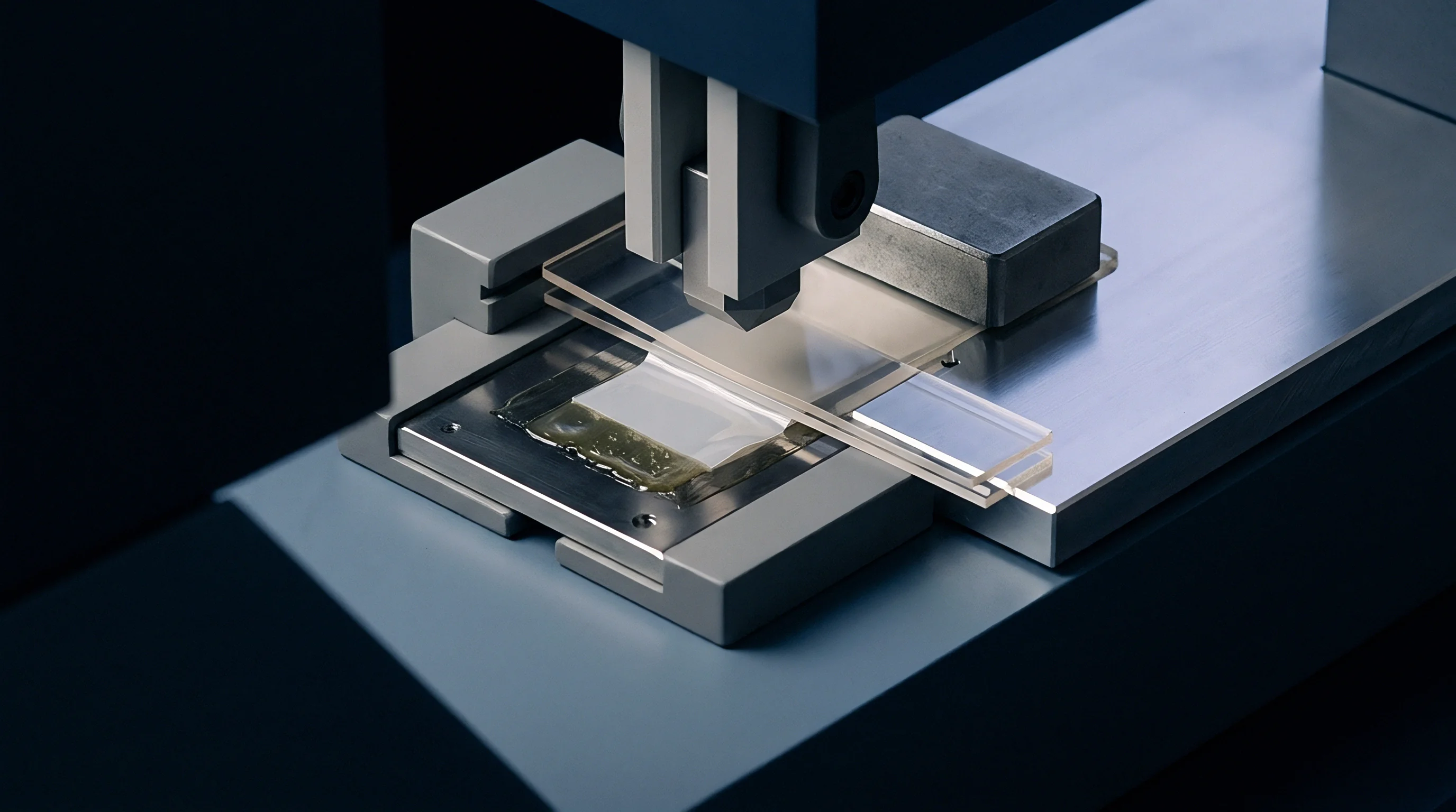
Excessive manual leverage on toggle clamps frequently bypasses the intent of technical drawings. Hand-operated destaco-style clamps provide substantial mechanical advantage, enabling press operators to exert several hundred newtons of localized force across small plastic tabs. When an operator forces an out-of-spec moulding into a rigid fixture using manual levers, the part flexes into temporary compliance.
Probing the part under this condition generates flawless CMM inspection reports while masking severe process instability at the moulding machine.
Polymer relaxes under load. Semicrystalline thermoplastics exhibit rapid viscoelastic stress relaxation when clamped. A polypropylene bumper tab clamped with an initial load of 40 newtons drops to 28 newtons within five minutes as polymer chains rearrange under ambient heat.
Fixture calibration procedures evaluate this force decay, establishing standardized time windows between part loading and tactile probing to maintain consistent datum contact without inducing progressive creep deflection during long measurement programs.

Pneumatic and Manual Actuator Regulation
Pneumatic clamping fixtures replace unpredictable operator manual force with regulated line pressure. Miniature pneumatic cylinders equipped with precision pressure regulators deliver repeatable clamping force cycles across multiple operator shifts. Calibration technicians hook digital pressure sensors into the pneumatic manifold to verify line pressure stability, verifying that line fluctuations from factory air compressors do not alter cylinder stroke forces at the fixture tips.
Elastomer tips fitted to clamp pressure feet distribute holding force across broad contact zones to prevent cosmetic marking of textured surfaces. Friction masks clamping force. Polyurethane contact pads degrade through oil absorption and repeated compression cycles, hardening from an initial 70 Shore A durometer to brittle states that concentrate pressure on narrow edges.
Annual calibration protocols require durometer testing and thickness verification of all resilient clamp contact pads, replacing hardened tips to preserve uniform load distribution.
Clamping forces calibrated beyond polymer yield stress induce permanent creep deformation during standard coordinate measuring cycles.
Clamping pressure applied beyond the threshold required to seat the datum pad flattens genuine mould warpage into artificial compliance.

Uncertainty
Measurement uncertainty in nonrigid plastic inspection incorporates fixture dimensional errors, machine repeatability limits, and ambient environmental variations. Deflection alters measured profile. Calculating total measurement uncertainty according to the Guide to the Expression of Uncertainty in Measurement requires metrologists to isolate each contributor within the inspection loop.
The restraint fixture forms the single largest contributor to overall uncertainty, frequently introducing errors twice as large as the coordinate measuring machine volumetric probing uncertainty itself.
Thermal expansion shifts datums. While standard metrology takes 20 degrees Celsius as the reference baseline, production fixtures constructed from 6061-T6 aluminum expand at 23 micrometers per meter per kelvin. A fixture measuring 1,500 mm across for an instrument panel carrier experiences a dimensional expansion of 0.17 mm when shop temperatures rise from 20 to 25 degrees Celsius.
If calibration occurs without mathematical temperature compensation, this thermal growth shifts pin centers and pad datums, inducing false deviations into the plastic part quality dossier.
| Uncertainty Contributor | Probability Distribution | Divisor | Standard Uncertainty (mm) | Percentage of Total Budget |
|---|---|---|---|---|
| CMM Volumetric Probing (ISO 10360-2) | Normal | 2.000 | 0.0035 | 4.2 % |
| Fixture Net Pad Calibration Uncertainty | Normal | 2.000 | 0.0075 | 9.1 % |
| Differential Thermal Expansion (Fixture vs Part) | Rectangular | 1.732 | 0.0210 | 25.4 % |
| Clamping Force Variation and Local Indentation | Rectangular | 1.732 | 0.0160 | 19.3 % |
| Datum Pin Clearance and Part Float | Triangular | 2.449 | 0.0145 | 17.5 % |
| Polymer Viscoelastic Creep During Inspection | Rectangular | 1.732 | 0.0205 | 24.5 % |
| Combined Expanded Uncertainty (k = 2) | 0.0784 mm at 95% Confidence Interval | |||

Thermal Drift and Coefficient Mismatch
Thermal coefficient disparities between the calibration artifact, the fixture base plate, and the measured plastic part complicate shop-floor verification. Aluminum expands at 23 parts per million per kelvin. Unfilled polypropylene expands at approximately 150 parts per million per kelvin, nearly seven times faster than the metallic fixture base.
An engineering resin containing 30 percent glass fibers exhibits anisotropic thermal shrinkage, expanding at 30 parts per million parallel to the melt orientation path and 80 parts per million perpendicular to flow lines.
Temperature gradients across large checking fixtures generate non-linear bending moments in structural weldments. Direct sunlight from shipping bay doors or cooling drafts from overhead ventilation units create localized temperature deltas across long fixture wings. Structural steel tubing subjected to a 3-degree temperature differential between top and bottom surfaces bows visibly, distorting net pad coplanarity.
Metrology protocols establish soaking intervals of at least twelve hours inside the temperature-controlled CMM enclosure before executing calibration certifications on major structural sub-frames.

Measurement System Analysis on Restrained Parts
Qualifying an inspection fixture demands comprehensive Gauge Repeatability and Reproducibility studies under production conditions. Ten representative mouldings spanning the expected process window undergo repeated loading cycles by three independent quality operators across distinct shifts. High operator-to-operator variance indicates ambiguous clamping sequences or inconsistent manual clamping force, pointing directly to flaws in the fixture operating instruction or mechanical clamp design.
Evaluating gauge capability requires total fixture-induced variation to consume less than ten percent of the component dimensional tolerance band for high-capability processes. When measurement system analysis reports gauge error between ten and thirty percent, quality managers may issue conditional fixture approval, provided the moulding process maintains a capability index above 1.67. Any fixture measurement system consuming greater than thirty percent of tolerance faces immediate mechanical rejection, mandating structural rework of resting pads, locator pins, and clamp linkages before part shipping authorisations proceed.
When thermal drift inside the fixture structure escapes the calibration budget, entire production lots face rejection at assembly despite passing receiving inspection at the moulding plant.


Upkeep
Ongoing maintenance preserves the mechanical integrity of CMM restraint fixtures over continuous automotive and industrial production cycles. Worn bushings introduce play. Production fixtures experience thousands of clamping cycles each month, leading to mechanical wear on hardened steel surfaces, abrasive erosion of aluminum resting pads, and contamination from plastic flash or shop dust.
Without a strict maintenance schedule, subtle physical degradation steadily erodes the measurement buffer, resulting in undetected dimensional drift across production shifts.
Toolroom verification confirms alignment. Periodic calibration intervals are determined by production volume, resin abrasiveness, and structural fixture materials. An unreinforced polyethylene component inspecting on an aluminum fixture can sustain annual calibration intervals.
A 40 percent glass-fiber reinforced polyphenylene sulfide moulding running high volumes requires quarterly recalibration, as abrasive glass fibers embedded in part flash abrade datum pins and net pads with every loading stroke.
Preventative Maintenance and Contact Pad Wear
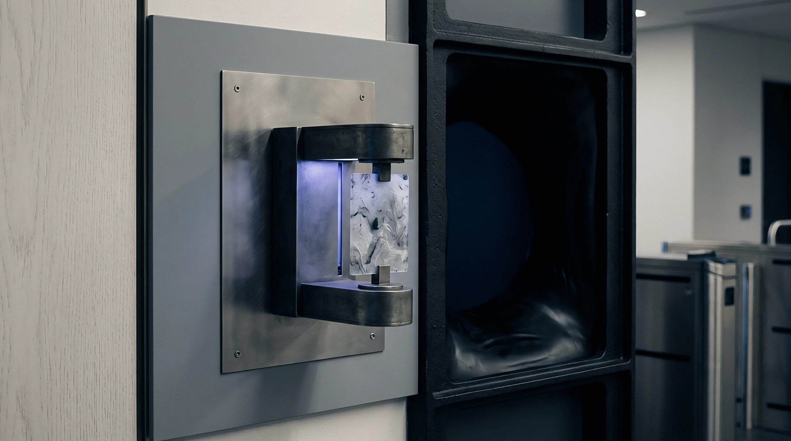
Routine maintenance schedules establish clear inspection criteria for every wearable mechanical interface on the fixture. Contaminants such as resin flakes, release agent residue, and particulate matter gather on resting pads, raising the component above its calibrated datum height. A single layer of compressed polymer dust measuring 0.03 mm in thickness offsets the part sufficiently to trigger false profile rejections on tight class-A surface tolerances.
- Solvent pad degreasing removes accumulated mould release agents, oil films, and shop airborne grease that attract particulate debris to critical resting surfaces.
- Bushing wear measurement checks bore clearances using calibrated plug gauges to identify egg-shaped bore wear before pin play compromises positional accuracy.
- Fastener torque auditing verifies that mounting bolts securing risers and locator blocks to the baseplate remain torqued to specified engineering limits.
- Clamp pivot lubrication prevents uneven mechanical drag in toggle linkages that would otherwise distort the vector of applied clamping loads.

Recalibration Triggers for Production Tooling
Unscheduled calibration events occur whenever structural damage or abnormal measurement data surfaces during regular production runs. Dropping a heavy steel clamp onto a locator block or accidental collisions between the CMM motorized probe head and a fixture riser demand immediate withdrawal of the unit from the inspection cell. Toolroom technicians execute a complete coordinate re-survey before returning the fixture to service.
Tooling engineering changes also trigger mandatory recalibration workflows. When mould revisions modify part wall thickness, gate locations, or stiffening rib geometry, the free-state warpage behavior of the component shifts. The existing clamp positions or resting pads may no longer align with structural support nodes, creating localized bending stresses during clamping.
Metrologists and tool designers must re-evaluate the restraint scheme against the modified shrinkage model, updating fixture pad coordinates and clamp pressures to match the revised engineering revision level.
Whether dynamic bushing erosion during repeated high-volume clamping cycles can be monitored continuously through embedded strain sensors remains unresolved across multi-cavity automotive exterior programs.