Computed Tomography Calibration Phantoms for Thick Thermoplastic Verification
Material-matched polymer phantoms eliminate scatter and beam hardening errors in computed tomography, ensuring accurate thick thermoplastic tooling buyoff.


Geometry
Wall sections exceeding eight millimeters in semi-crystalline thermoplastics alter the physics of industrial X-ray inspection. Penetration through thirty millimeters of polyoxymethylene or high-density polyethylene reduces photon counts while shifting the mean energy of a polychromatic X-ray spectrum toward higher values. Metrology laboratories running standard metal calibration artifacts frequently register false wall positions on thick plastic parts.
The density differential between a titanium calibration cylinder and an unfilled thermoplastic resin produces disparate transmission profiles. Calibration artifacts manufactured from matching polymer resins establish identical absorption characteristics, eliminating grey-value scaling errors at the boundary of thick components.
Thick polymer sections absorb unevenly.
Attenuation Gradients across Heavy Structural Cross Sections
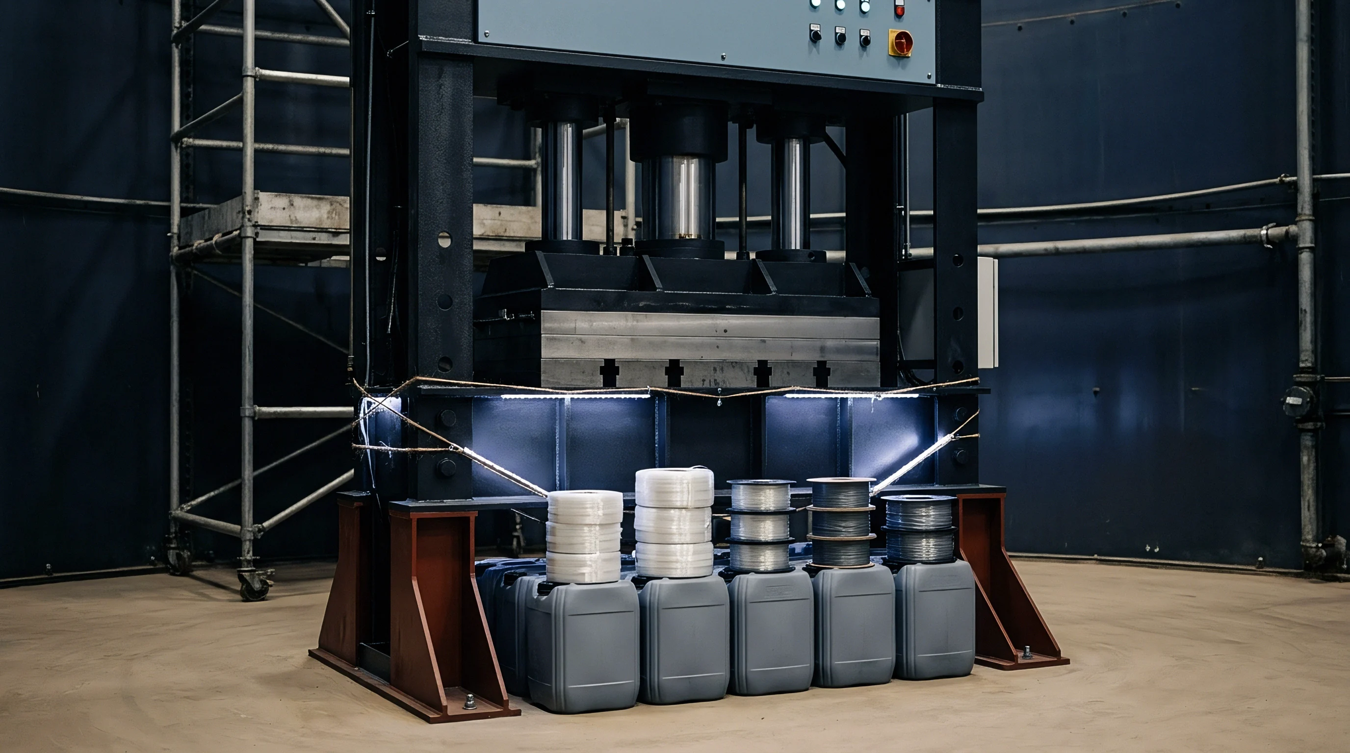
X-ray absorption through polymers follows the Beer-Lambert formulation, wherein beam intensity drops exponentially based on mass attenuation coefficients and linear thickness. At tube voltages between 130 kV and 225 kV, Compton scattering dominates over photoelectric absorption in low-atomic-number elements like carbon, hydrogen, and oxygen. When the path length through an injection-moulded hub or structural boss spans twenty-five millimeters, peripheral voxels experience a softer spectrum than central voxels.
This spectral filtration generates artificial gradients in grey values across homogenous bulk material. Standard thresholding routines interpret these variations as physical density shifts or shrinkage voids.
Thick cross sections create internal grey-scale drift that mimics resin degradation.
Tooling engineers attempting to qualify mould cavities for thick-walled components encounter severe verification disputes when relying on conventional coordinate measuring machines or uncalibrated computed tomography. Tactile styli cannot inspect internal cooling galleries, closed gas-assist channels, or complex core-pin undercuts without sectioning the part. Destructive sawing relieves residual moulding stress, warping the part before a surface plate inspection can take place.
Computed tomography captures the unconstrained state of the moulding. Dimensional accuracy remains tied directly to voxel size determination, which wanders when the calibration standard does not match the specimen material.

Step Wedge Reference Standards for Density Matching
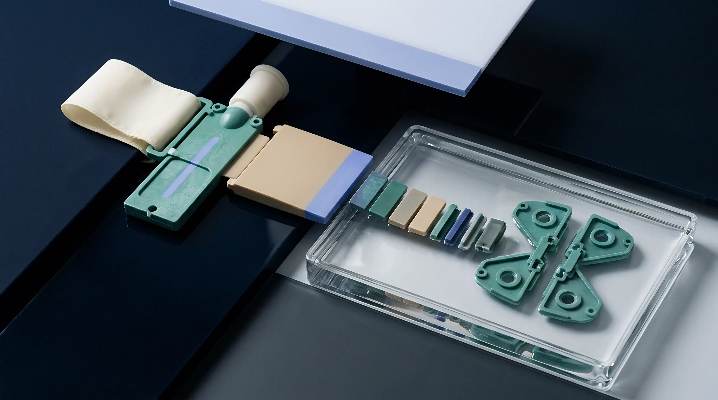
Physical calibration standards configured as stepped plates provide discrete transmission tiers matching the thickness variations found on heavy injection mouldings. Machining a step wedge directly from extruded polyoxymethylene copolymer or polyetheretherketone stock preserves the bulk attenuation characteristics of the production run. Each plateau presents a calibrated thickness measured on a contact interferometer under temperature-controlled conditions.
Exposing the stepped artifact to the cone beam establishes an empirical transmission curve across the entire acceleration potential range of the X-ray tube.
Crystallinity alters volumetric shrinkage.
Extruded thermoplastic stock used to machine calibration blocks carries a thermal history different from injection-moulded cavities. Annealing the reference stock at one hundred forty degrees Celsius relieves frozen orientation stresses that induce subtle density variations. The resulting artifact maintains consistent mass attenuation across every stepped tier.
The metrology setup aligns the steps along the central ray to minimize penumbral blurring caused by focal spot blooming at elevated tube wattages.
- Extruded polyoxymethylene plate stock annealed for four hours provides uniform crystal distribution across step thicknesses from five to fifty millimeters.
- Unfilled polyetheretherketone blocks ground to parallel tolerances within two micrometers deliver reference absorption values for high-heat engineering applications.
- Ultra-high molecular weight polyethylene profiles offer low-density baselines for verifying porous core structures and thick fluid-handling manifolds.
- Glass-filled polyamide billets containing thirty percent short fibers serve as structural matrix standards for validating filler orientation effects.
Thick-walled mouldings stabilize dimensions only after internal thermal gradients reach equilibrium with the room environment.
Sphere
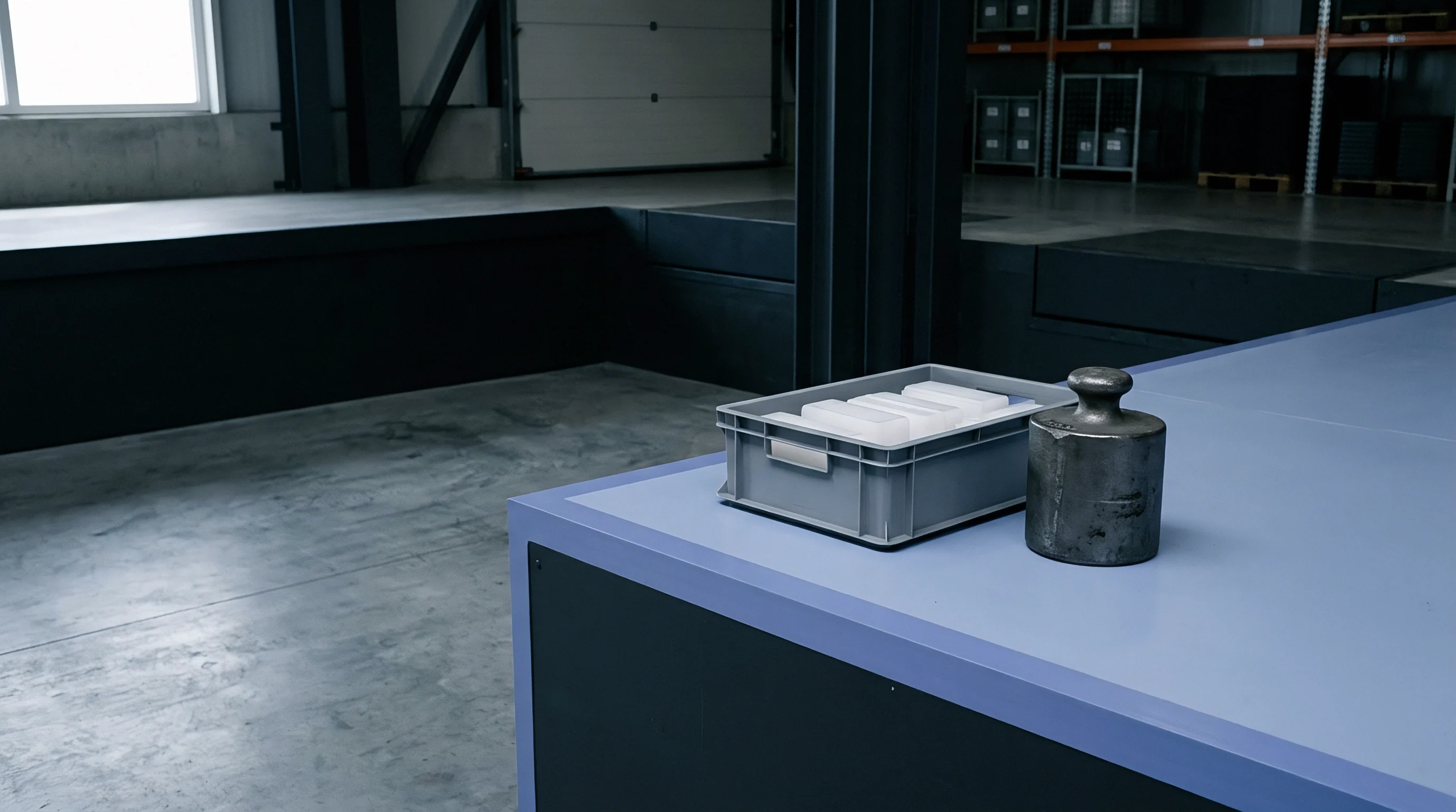
Ruby or silicon nitride balls mounted on low-expansion carbon fiber shafts define the spatial coordinates of computed tomography calibration assemblies. The separation distance between spherical centers provides a reference length independent of surface extraction algorithms. Surface determination on a polymer boundary introduces threshold uncertainties of several voxels.
The center of a sphere, calculated via Gaussian least-squares fitting of thousands of surface points, remains unaffected by systematic surface threshold offsets. Multi-sphere calibration trees enable absolute voxel size calibration across the measurement volume.
Probing length error remains within four micrometers when calibrated ruby reference centers verify the reconstruction voxel scale under VDI/VDE 2630 Part 1.3 at twenty degrees Celsius.
Thermal expansion of thermoplastic materials complicates the mechanical support architecture of calibration phantoms. A polyoxymethylene block expands at roughly one hundred ten parts per million per Kelvin. Enclosing ceramic spheres inside a solid polymer casing risks displacement of the sphere centers during ambient cabin temperature shifts.
Industrial CT systems generate heat through tube operation, target cooling, and detector electronics, warming the enclosure interior by up to three Kelvin during extended multi-angle scans.

Calibrated Coordinate Distances in Low Density Enclosures
Carbon fiber reinforced polymers exhibit near-zero coefficients of thermal expansion along their longitudinal fiber axis. Suspending silicon nitride spheres on pultruded carbon fiber rods within a thin-walled polymer sleeve isolates the reference geometry from the thermal growth of the surrounding plastic. The ceramic spheres provide sharp X-ray contrast against both air and polymer backgrounds.
The high radiopacity of the spheres allows automated sphere-detection software to isolate the centers despite significant noise in raw projections.
Ruby spheres resist mechanical wear.
Calibration assemblies designed for thick thermoplastic inspection combine a carbon fiber ball tree positioned adjacent to a stepped polymer body. This hybrid arrangement decouples spatial scaling calibration from material-specific beam hardening compensation. Spatial scaling links directly to the physical distance between sphere centroids traced to national metrology standards.
Grey-value calibration links to the transmission through the stepped polymer sections. Running both geometries in a single calibration trajectory eliminates system drift between parameter setups.
How Attenuation Gradients Shift Edge Detection in Heavy Sections?
Penetration through variable wall thicknesses alters the local contrast ratio across part boundaries. Software implementing ISO fifty percent thresholding calculates the edge as the midpoint between background air and the material plateau. In a moulding featuring twenty-millimeter structural ribs meeting a five-millimeter base plate, the internal material plateau drops in grey value toward the center of the rib due to scatter and beam hardening.
The threshold value calculated for the thin plate misplaces the edge of the thick rib, reporting a phantom dimensional shift of up to seventy micrometers.
Edge determination dictates dimensional error.
Addressing edge displacement requires scanning calibrated step cylinders containing embedded ceramic markers. The physical diameter of each cylinder step establishes an empirical correction factor for the surface determination algorithm at each specific wall thickness. The operator applies this correction during post-processing surface extraction routines.
- Mount the multi-step polymer phantom securely on the rotary table chuck using low-density expanded polystyrene fixtures.
- Align the rotation axis perpendicular to the center of the cone beam using a dial indicator with a sapphire contact point.
- Acquire twelve hundred projection images across three hundred sixty degrees with an integration time of one second per frame.
- Reconstruct the volumetric data set using filtered back-projection with a Feldkamp-Davis-Kress algorithm.
- Fit spherical centroids using three-dimensional Gaussian feature extraction to calculate global voxel magnification error.
- Extract cylinder boundary surfaces using local gradient thresholds calibrated against contact measurement reference values.
VDI/VDE 2630 Part 1.3 establishes that structural length measurement errors must account for workpiece-induced absorption artifacts through documented substitution measurements on material-matched calibration artifacts.


Artifact
Reconstruction algorithms convert two-dimensional X-ray attenuation projections into three-dimensional voxel arrays by assuming monochromatic radiation. Industrial open-tube sources emit continuous bremsstrahlung spectra with characteristic radiation spikes determined by the target material, typically tungsten. Lower-energy photons absorb more rapidly within the initial few millimeters of thermoplastic material than higher-energy photons.
The transmitted beam carries an elevated effective energy, skewing the linear attenuation relationship. The reconstruction engine renders this non-linear absorption as a cupping defect, making solid plastic cores appear less dense than external skin layers.
Unfiltered polychromatic spectra induce cupping.
VDI/VDE 2630 Part 1.4 requires documented validation of beam hardening correction filters whenever wall thicknesses exceed twelve millimeters in low-attenuation polymers.
Cupping errors alter wall thickness measurements by distorting voxel grey values across the component. A solid injection-moulded POM gear blank with a thirty-millimeter hub exhibits artificial density depressions in its volumetric core. Quality inspectors misidentify these depressions as micro-porosity or processing voids.
Toolmakers cutting steel on the basis of these false void reports alter packing pressures and runner geometries unnecessarily, degrading actual production stability. Physical filtration combined with algorithmic compensation resolves this diagnostic confusion.

Beam Hardening Compensation in Polychromatic Spectra
Hardware pre-filtration attenuates soft X-ray photons before the beam strikes the thermoplastic workpiece. Placing a thin sheet of copper or brass directly at the tube collimator outlet hardens the spectrum prior to specimen entry. For thick POM or nylon parts, a zero-point-five millimeter copper filter removes the low-energy photon tail that causes surface absorption spikes.
The resulting transmission spectrum behaves more linearly through the plastic, reducing cupping artifacts to values below the voxel noise floor.
Copper prefilters harden the beam.
Algorithmic beam hardening correction models the polyenergetic response mathematically. The operator scans a stepped calibration cylinder of the identical resin grade to generate an empirical linearization polynomial. The CT reconstruction workstation applies this polynomial to correct the raw sinogram data prior to filtered back-projection.
Comparing uncorrected and linearized reconstructions demonstrates complete elimination of the false core-density depression.
| Phantom Material | Density (g/cm³) | Linear Attenuation Coefficient (1/cm) | Coefficient of Thermal Expansion (10⁻⁶/K) | Probing Error Influence |
|---|---|---|---|---|
| Polyoxymethylene Copolymer (POM-C) | 1.41 | 0.24 | 110 | Matches baseline injection moulding absorption |
| Polyetheretherketone (PEEK) | 1.30 | 0.21 | 45 | Stable across elevated cabin temperatures |
| Polytetrafluoroethylene (PTFE) | 2.16 | 0.38 | 135 | Excessive expansion during long scan cycles |
| Silicon Nitride (Si₃N₄) Spheres | 3.20 | 0.78 | 3.2 | Negligible thermal drift for coordinate centers |
| Aluminium Alloy 6061 | 2.70 | 0.82 | 23 | Induces severe streak artifacts against polymers |

Threshold Inaccuracies at Variable Penetration Depths
Local surface determination routines evaluate gradient peaks across voxel grey-value profiles. When a thick section generates significant forward scatter, background noise levels rise across the flat panel detector. The increased noise reduces the slope of the edge gradient, widening the uncertainty band for edge placement.
A flatter gradient forces software algorithms to search across larger spatial kernels, integrating noise and biasing the measured diameter of internal voids or fluid channels.
The injection moulder claims that apparent core porosity represents scan noise rather than true shrinkage voiding.


Scatter
Compton interactions in thick low-atomic-number materials produce secondary photons that deviate from the primary geometric trajectory. These scattered photons strike detector pixels away from their correct projection ray, superimposing a low-frequency background glare over the projection image. As thermoplastic section thickness increases from ten millimeters to forty millimeters, the scatter-to-primary ratio rises rapidly.
This secondary radiation reduces global image contrast, suppresses detail visibility, and creates dark streak artifacts between dense features such as metallic inserts or adjacent structural ribs.
Scattering fogs the detector array.
Flat panel detectors equipped with cesium iodide scintillators exhibit sensitivity to scattered photons across a broad energy spectrum. In industrial cone-beam configurations, large cone angles expose the entire detector area to scatter generated throughout the part volume. Fan-beam collimation drastically reduces scatter capture by restricting exposure to a single slice plane, though data acquisition times increase by orders of magnitude.
Industrial verification of thick components balances scan duration against tolerable measurement uncertainty.
Collimation and Hardware Filtering Tradeoffs
Mounting an anti-scatter grid directly over the detector face absorbs photons entering at oblique angles. Lead septa aligned with the focal spot strip away secondary scatter while transmitting primary geometric rays. For thick plastic parts scanned at high tube currents, an anti-scatter grid improves edge sharpness and suppresses streak artifacts.
The grid introduces mechanical striping artifacts on projection images that require software flat-field correction before reconstruction.
Voids generate internal stress concentrations.
Physical apertures positioned between the X-ray target and the workpiece constrain the cone beam precisely to the active inspection envelope. Restricting the irradiated volume limits the generation of scatter within unused portions of the plastic component or surrounding fixturing. Fixturing elements manufactured from low-density polymethacrylimide foam produce negligible scatter compared to conventional aluminum or mechanical clamping vices.
- Dark streak generation across polymer ribs separating internal structural cavities distorts automatic wall thickness evaluation tools.
- Edge blooming effects around metallic press-fit bushings cause threshold extraction routines to report undersized polymer inner diameters.
- Global contrast degradation prevents the segmentation of micro-voids smaller than three voxel lengths within thick boss sections.

Whose Traceability Standard Governs Coordinate Measurement Traceability?
Calibration certificates for coordinate measuring systems reference traceable physical lengths maintained by national metrology institutes. In tactile coordinate metrology, ISO 10360-2 defines acceptance testing using calibrated step gauges and gauge blocks. For computed tomography systems, ISO 10360-8 and VDI/VDE 2630 Part 1.3 define acceptance tests using calibrated sphere assemblies.
The traceability chain links the pixel pitch and manipulator kinematics to optical or laser interferometry standards.
Toolmakers measure cold steel dimensions.
Traceability issues emerge when extending calibration certificates obtained on miniature carbon-fiber sphere trees to the measurement of thick plastic mouldings. A CT scanner holding three-micrometer probing error on a small ruby phantom may display twenty-micrometer errors when inspecting a thick POM manifold. Workpiece-induced physical effects, including scatter and beam hardening, degrade the achievable precision of the system.
Validating measurement capability on thick plastics demands that verification testing incorporate an artifact presenting identical material attenuation and equivalent path lengths.
| Section Thickness (mm) | Mean Transmission (%) | Scatter-to-Primary Ratio | Probing Error MPE (µm) | Edge Shift Offset (µm) |
|---|---|---|---|---|
| 5.0 | 78.4 | 0.08 | ± 4.5 | + 1.2 |
| 15.0 | 52.1 | 0.24 | ± 7.2 | + 4.8 |
| 30.0 | 28.6 | 0.58 | ± 14.0 | + 12.5 |
| 50.0 | 11.2 | 1.15 | ± 26.5 | + 28.0 |
Failing to account for scatter-induced edge bias leads to unnecessary tooling modifications that permanently ruin precision injection mould steel.


Appraisal
Capital commitments for multi-cavity injection tools producing thick structural components depend heavily on dimensional buyoff protocols. A single cavity tool for a twenty-five millimeter thick automotive suspension bush or hydraulic valve body represents significant capital investment. Modifying cavity geometry through electric discharge machining or precision milling requires accurate deviation maps.
If tomographic verification misinterprets scatter-induced edge shifts as steel discrepancies, toolmakers cut away steel in the wrong direction. Replacing lost steel requires welding or building new inserts, delaying SOP dates by months.
Steel modifications destroy capital.
Thermal stabilization takes four hours.

Dimensional Compliance and First Article Signoff
First article inspection reports generated through computed tomography provide thousands of measurement points across complex internal geometries. The buyer reviews these point clouds to verify geometric dimensioning and tolerancing parameters under ISO 1101. When checking positional tolerances of deep internal cores relative to external datum planes, voxel scale stability dictates pass or fail results.
Calibrating the scanner with a material-matched phantom immediately prior to scanning production parts locks the measurement uncertainty envelope.
Detector calibration prevents ring artifacts.
Procurement agreements specify measurement uncertainty boundaries according to ISO 14253-1. The decision rule defined in ISO 14253-1 reduces the specification zone by the expanded measurement uncertainty. If uncompensated scatter and beam hardening expand the CT uncertainty to twenty micrometers on a fifty-micrometer tolerance, forty percent of the allowable manufacturing bandwidth disappears.
Calibrated phantoms compress the measurement uncertainty, restoring acceptable process capability indices for the moulder.

Tooling Adjustment Budgets from Validated Tomographic Scans
Sinking marks on thick show-surfaces correlate with volumetric shrinkage differentials occurring during the cooling phase of injection moulding. When cooling thick sections, the core remains molten while exterior skin layers solidify, pulling material inward. Computed tomography visualizes both the exterior sink profile and the internal void network simultaneously.
Tooling engineers use calibrated tomographic slices to calculate exact volumetric displacement, adjusting pack-and-hold profiles on the moulding press before commissioning steel modifications.
Sink marks distort surface normals.
A tooling adjustment cycle costs between five thousand and thirty thousand euros per iteration depending on tool size and slide complexity. Using uncalibrated CT data often triggers three or four iterative steel recuts. A calibrated reference phantom workflow stabilizes first-shot surface extraction within acceptable measurement uncertainty bands, resolving tooling iterations on the initial modification run.
Buyers protect project timelines by requiring verified calibration logs with every submitted inspection dataset.
Whether metrology standards committees will formally standardize polymer-specific calibration phantoms alongside traditional titanium and ruby reference structures remains an unresolved question in coordinate metrology.