Cavity Pressure Transducer Installation Basics in Micro Injection Tooling
Precision cavity pressure transducer installation in micro injection tooling requires sub-five-micron pocket tolerances and rigid force transmission pin alignment.
Bore

Pocket Machining and Micro Plate Spatial Allocation
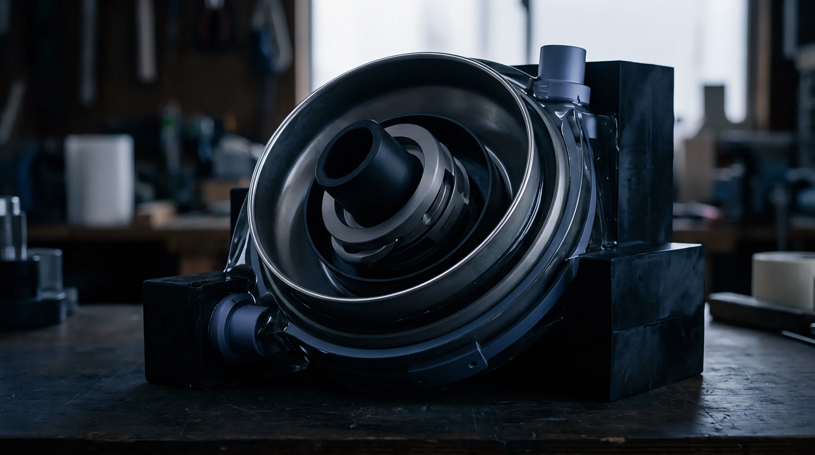
Tooling for micro injection moulding leaves little room for error when shot weights drop below 0.1 grams and cavity walls thin under 200 micrometres. Fitting pressure sensors into inserts this small requires tightly controlled pocket geometry; under cavity pressures up to 2000 bar, any poorly supported area invites localized yielding or transducer damage. Direct piezoelectric transducers sit on a precision seat machined directly behind the cavity wall, whereas indirect systems rely on force transmission members contacting a remote transducer element.
Perpendicularity between the transducer seating face and the mounting hole centerline must stay within 0.005 millimetres. Tilting past 0.05 degrees loads the quartz element unevenly, concentrating stress along one edge until the diaphragm cracks or signal output turns non-linear. Sinker electrical discharge machining produces the required Ra 0.2 micrometre surface finish on the internal shoulder without inducing micro-cracks in hardened tool insert materials.
A seating shoulder angular error of 0.1 degrees reduces sensor signal accuracy by sixteen percent under micro-moulding peak pressures.
Space limits in multi-cavity micro tools force layout choices between direct cavity wall contact and indirect transmission. Micro parts rarely present sufficient surface area for a direct sensor diaphragm, which typically carries a minimum diameter of 1.0 to 1.8 millimetres. Direct installation remains restricted to runner channels or enlarged part features such as core pins or structural bosses.
Dimensional Thresholds for Micro Transducer Recesses
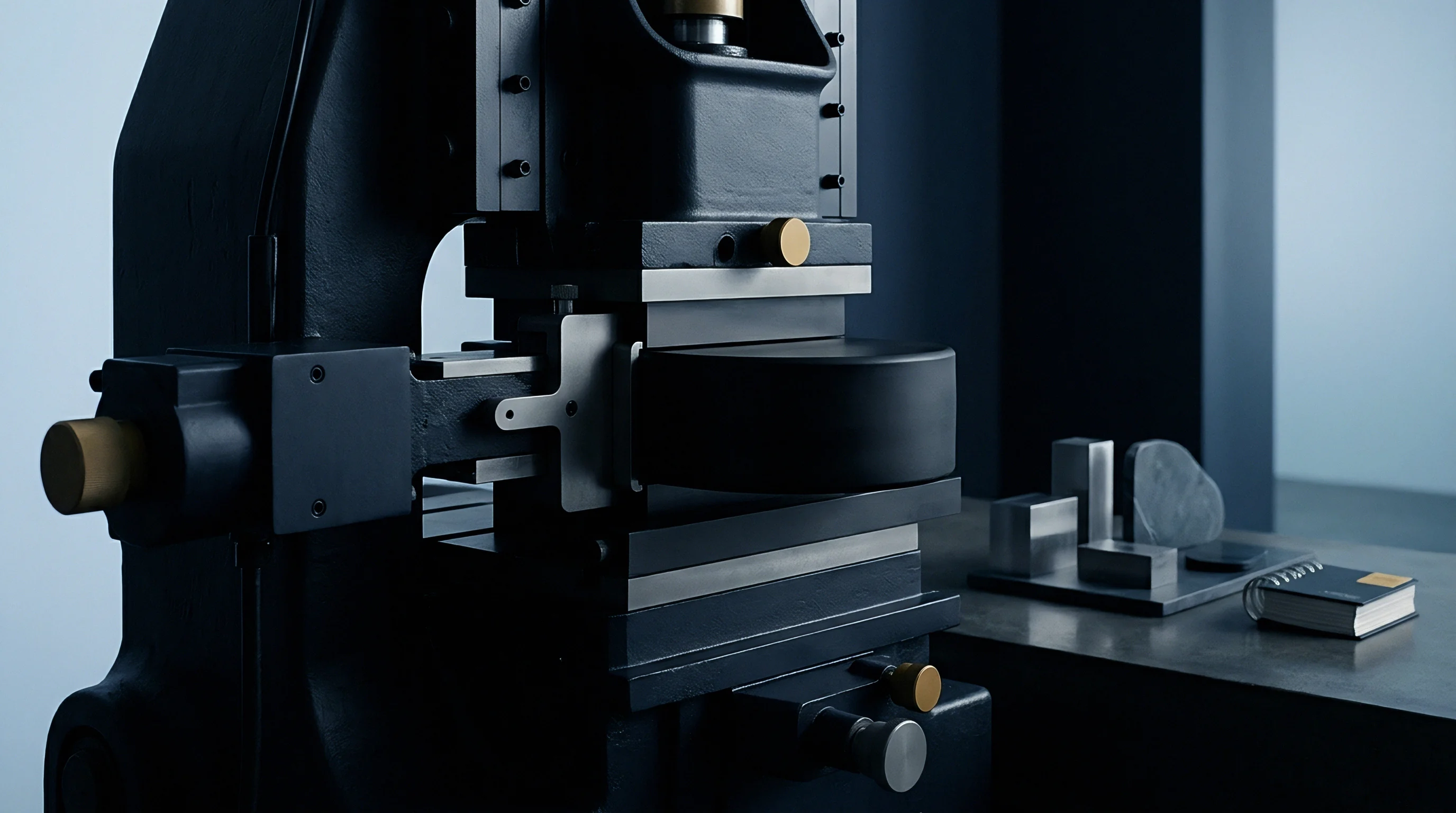
Pocket tolerances dictate whether signal calibration holds across continuous production cycles. Sinking deep blind holes with high depth-to-diameter ratios into hardened steel presents severe manufacturing challenges. Sinker EDM electrodes must incorporate precise orbital flushing channels to remove eroded particles, preventing micro-arc damage on the seating floor.
| Pocket Parameter | Direct Sensor (1.8 mm Diaphragm) | Indirect Sensor (Button Type) | Machining Process |
|---|---|---|---|
| Bore Diameter Tolerance | +0.005 / -0.000 mm | +0.010 / -0.000 mm | Precision Reaming / Wire EDM |
| Base Flatness | 0.002 mm | 0.003 mm | Sinker EDM Fine Polish |
| Concentricity to Pin Axis | 0.003 mm TIR | 0.005 mm TIR | Jig Grinding |
| Surface Roughness (Ra) | 0.2 µm | 0.4 µm | Micro-Erosion / Polishing |
Plate flex under peak packing pressure corrupts transducer baseline signals. When the tool plate flexes beyond 0.003 millimetres around the pocket, the sensor body experiences mechanical binding. That shift alters the internal pre-load, inducing fictitious pressure signals that skew closed-loop V/P transition controls.
Letting concentricity drift between the guide clearance hole and the sensor base causes total sensor failure within fifty thousand production cycles.


Pin

Force Transmission Mechanics in Sub-Millimetre Cavities
Indirect pressure sensing relies on ejector pins or dummy transmission pins to transfer melt pressure from the cavity to a remote load washer. In micro moulding, these pins frequently feature active diameters ranging between 0.4 and 0.8 millimetres. Force acting on the pin face equals the cavity pressure multiplied by the cross-sectional area of the pin tip.
Small pin diameters drastically reduce the absolute force reaching the piezoelectric element.
A 0.5 millimetre pin under 1000 bar cavity pressure transmits a force of approximately 19.6 Newtons. That low force signal approaches the lower sensitivity limit of standard industrial piezoelectric load washers, making amplification and filtration critical for stable process control. Micro pins require precise axial alignment to eliminate sliding friction within the pin channel.

Frictional Losses and Clearance Fits
Friction along the pin guide surface absorbs force, preventing true cavity pressure transmission to the sensor. The clearance fit between the transmission pin and its guide hole controls both polymer flash entry and sliding friction levels. Micro moulding resin viscosity under high shear rates requires extraordinarily tight diametral clearances.
- Clearance Machining requires a diametral clearance between 0.002 and 0.004 millimetres to prevent liquid melt infiltration at 1800 bar.
- Guide Length Limitation restricts the contact length of the micro pin to three times its diameter, stepped down behind the land to lower friction.
- Surface Treatment applies physical vapour deposition titanium nitride coatings to reduce the coefficient of friction below 0.15 without lubrication.
- Axial Pre-Load Application sets an initial mechanical load of ten percent of full scale on the sensing element to eliminate mechanical backlash.
Pin deflection under lateral melt flow distorts force readings during early cavity filling. When viscous polymer enters the gate asymmetric to the pin axis, lateral bending forces push the pin against the cavity wall. This mechanical binding records as false cavity pressure spikes or delayed signal response.
Pin guide friction exceeding five percent of total transmitted force invalidates scientific moulding process transfer parameters.
Short contact lands combined with relieved shank diameters maintain structural alignment while eliminating drag along the primary tool plate.

Steel
Tooling Metallurgy and Seat Integrity
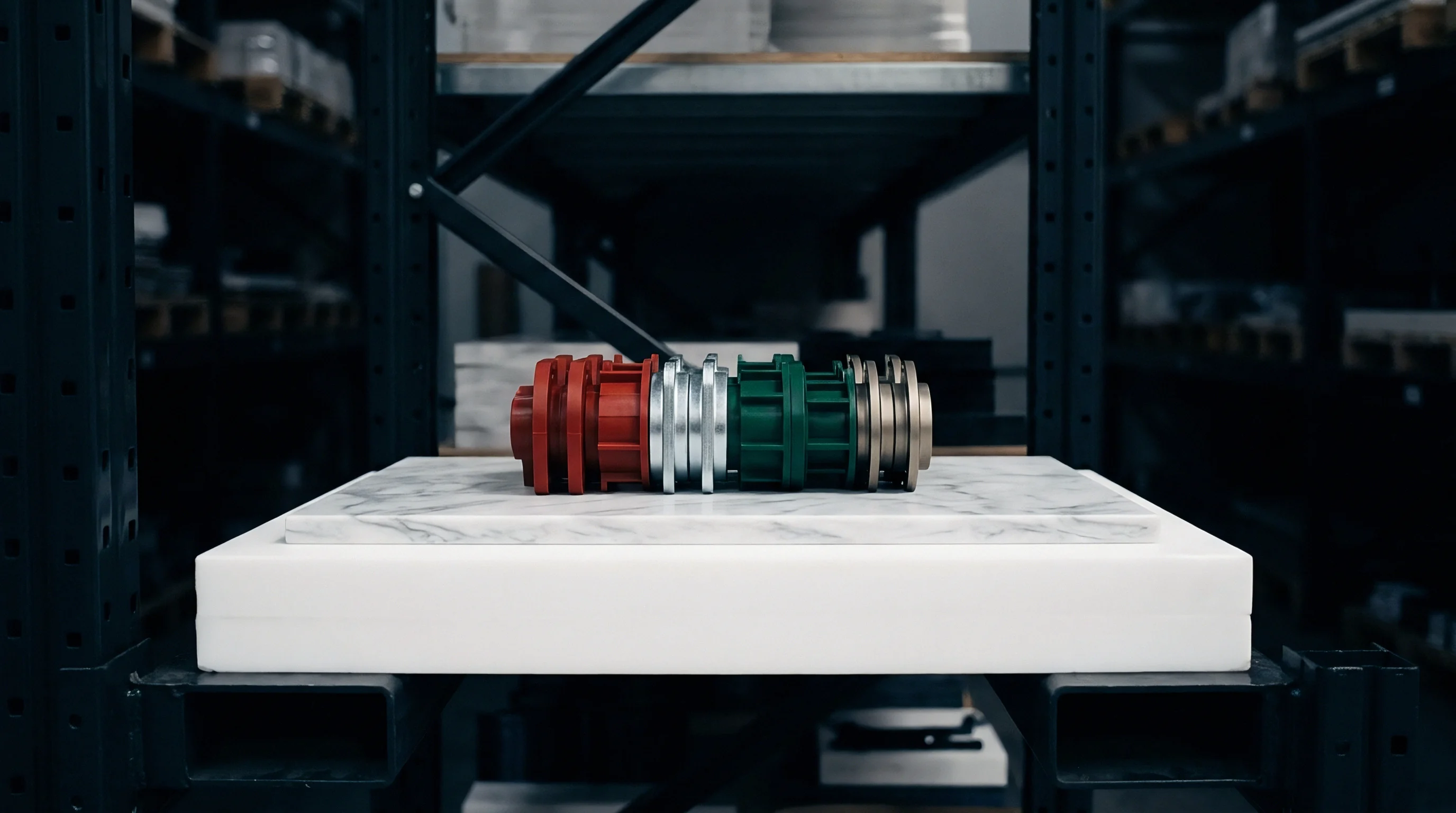
Selecting insert steel determines long-term sensor pocket stability under high cyclic thermal and mechanical loads. Corrosion-resistant stainless tool steels with high hardness maintain flat sensor seating faces across millions of injections. Through-hardened steels rated at 52 to 54 HRC resist localized plastic deformation beneath transducer load buttons.
Softer tool steels yield under concentrated sensor pre-loads. Localized compression creates micro-indentations on the pocket floor, causing the transducer to lose pre-load over consecutive thermal cycles. Loss of pre-load appears on press-side monitors as continuous zero-point downward drift.

How Does Load Button Alignment Impact Signal Output?
Misalignment between the transmission pin base and the sensor load button concentrates force onto the outer margin of the sensing element. Piezoelectric quartz discs produce charge directly proportional to uniform compressive strain. Non-uniform force distributions skew charge output, rendering factory sensor calibration constants inaccurate.
| Steel Grade | Hardness (HRC) | Thermal Conductivity (W/m·K) | Yield Strength (MPa) | Seat Indentation Resistance |
|---|---|---|---|---|
| 1.2344 / H13 | 48 – 52 | 24.5 | 1650 | Moderate |
| 1.2083 / 420 SS | 50 – 54 | 19.0 | 1700 | High |
| Stavax ESR | 52 – 54 | 20.0 | 1780 | High |
| Ampcoloy 940 | 28 – 32 | 208.0 | 680 | Unsuitable without Steel Bushing |
Tool steel thermal expansion alters sensor pre-load as the tool transitions from ambient temperature to operational setpoints. A mould heating from 20°C to 140°C expands differential distances based on material stack-up between the core plate, pin shoulder, and transducer housing. Designers calculate thermal expansion differences to prevent sensor crushing at operating temperature.
Charge amplifier software filters can compensate for baseline thermal drift, though physical expansion still alters the underlying mechanical pre-load on the crystal.

Cable
High-Impedance Signal Routing and Shielding
Piezoelectric sensors generate low electric charge signals measured in pico-Coulombs per bar. High-impedance signal transmission lines require complete isolation from machine vibration, electromagnetic interference, and thermal fluctuations. Micro tooling bases offer minimal internal routing channels, forcing signal wires into close proximity with high-power cartridge heaters and AC solenoid valves.
Coaxial cables carrying micro-charge signals demand armor-jacketed shielding grounded exclusively at the charge amplifier panel. Floating grounds at the tool base create ground loops that introduce 50/60 Hz noise into the cavity pressure curve. Electrostatic noise easily hides true cavity peak pressure events in small micro-moulding cavities.
Unshielded sensor cables running parallel to hot runner heater lines incur electrical noise amplitude exceeding five percent of full-scale output.
Routing Channels and Strain Relief Mechanics
Bending radii for micro coaxial cables must not drop below twenty millimetres. Tight bends fracture internal dielectric layers, creating triboelectric noise when the tool opens and closes rapidly. Machined wire channels inside mould plates incorporate smooth radii and retaining plates to lock cables against cyclic acceleration forces.
- Single Wire Isolation prevents crosstalk between adjacent multi-cavity pressure channels inside small mold bases.
- Rigid Frame Clamping fixes sensor connectors to the outer mold plate, protecting internal wiring from operator pull damage.
- Thermal Shielding Sleeves protect fluoropolymer-insulated wiring from direct contact with 200°C hot runner manifold blocks.
Moisture ingress into unsealed sensor connectors reduces insulation resistance below 1013 Ohms. Reduced insulation resistance causes rapid charge leakage, making static calibration and long cavity pack-phase monitoring impossible. Connectors require liquid-tight o-ring seals when installed near cooling line water channels.
Standard signal processing filters struggle to isolate genuine pressure changes from triboelectric noise generated by high-speed micro injection press clamp vibrations.

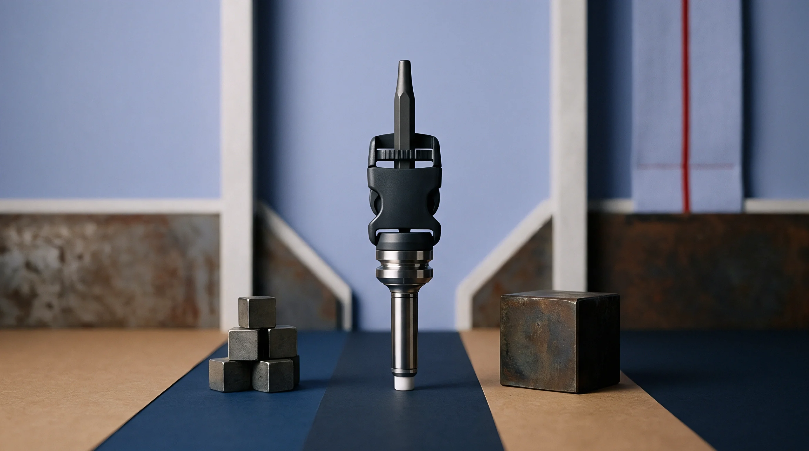
Proof
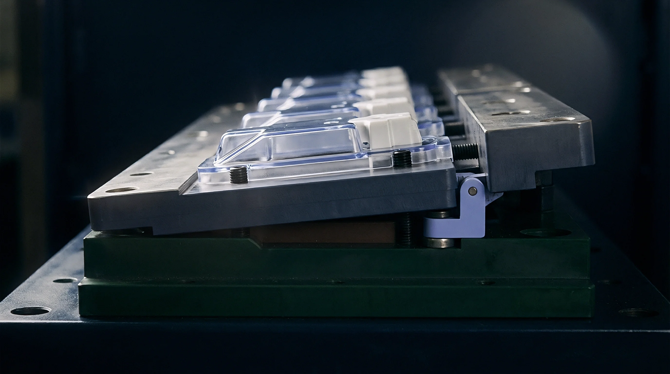
Pre-Load Verification and T1 Qualification Mechanics
Pre-load application establishes the mechanical baseline for cavity pressure measurement accuracy. Direct sensors require targeted torque limits applied to clamping nuts, while indirect sensors use spacer shims behind the load button. Machinists grind spacer shims in increments of 0.002 millimetres to set the precise pre-load force dictated by transducer manufacturers.
Over-tightening clamp nuts deforms the internal quartz crystal array, inducing permanent sensitivity loss. Under-tightening leaves physical gaps, producing signal delays during initial cavity filling. Mechanical pre-load checks take place using calibrated benchtop charge meters before installing the tool plate onto the press frame.
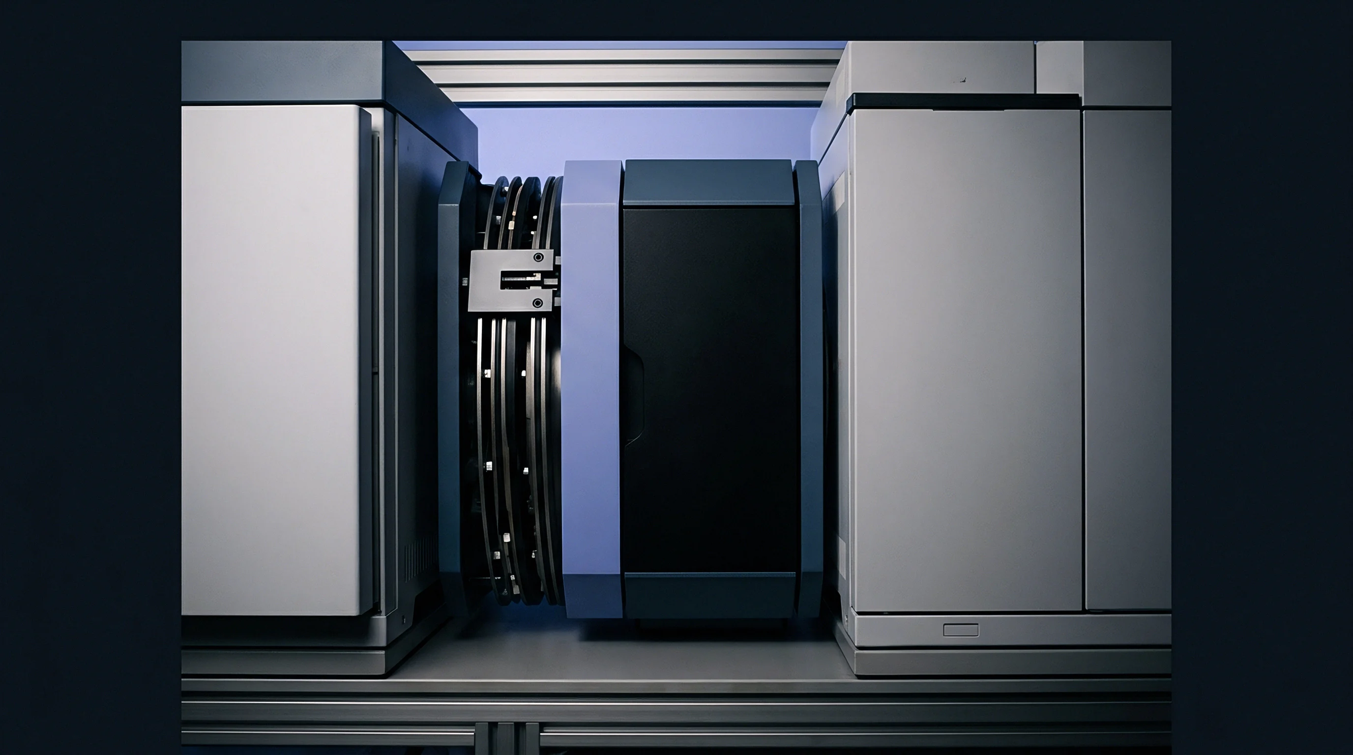
Calculated Pre-Load Shim Thickness Setup
Determining the exact shim thickness requires measuring the depth stack-up from the tool plate surface to the sensor seat. In an indirect button transducer installation with a nominal height of 5.000 millimetres, a required pre-load force of 500 Newtons, and an assembly spring rate of 100 Newtons per micrometre, stack dimensions govern final preload.
The necessary mechanical deflection equals 500 Newtons divided by 100 Newtons per micrometre, resulting in 5 micrometres of axial compression. Measuring the pocket depth gives 12.500 millimetres, and the transmission pin length measures 7.510 millimetres. The total relaxed stack height equals 12.510 millimetres, establishing an uncompressed projection of 10 micrometres above the pocket face.
A precision surface grinder reduces the shim thickness by 5 micrometres to hit the target 5-micrometre compression offset.
Mechanical pre-load values falling below eight percent of rated sensor capacity generate non-linear response curves during initial cavity filling.
Initial trial bring-up requires matching cavity pressure curves against machine hydraulic pressure profiles. Scientific moulding practices rely on cavity pressure peak timing to set velocity-to-pressure switchover points accurately. Transducers installed correctly reveal exact gate freeze times by detecting the inflection point where pressure decay changes slope during the cooling phase.
DIN 16742 Grade TG3 dimensional tolerances apply strictly once cavity pressure monitoring locks the volumetric fill and pack profiles across production runs.