Anisotropic Shrinkage Variance in Glass-Filled Polyamide Secondary Tooling Nests
Secondary tooling nests for glass-filled polyamide accommodate anisotropic shrinkage through floating datum pins aligned with transverse contraction vectors.
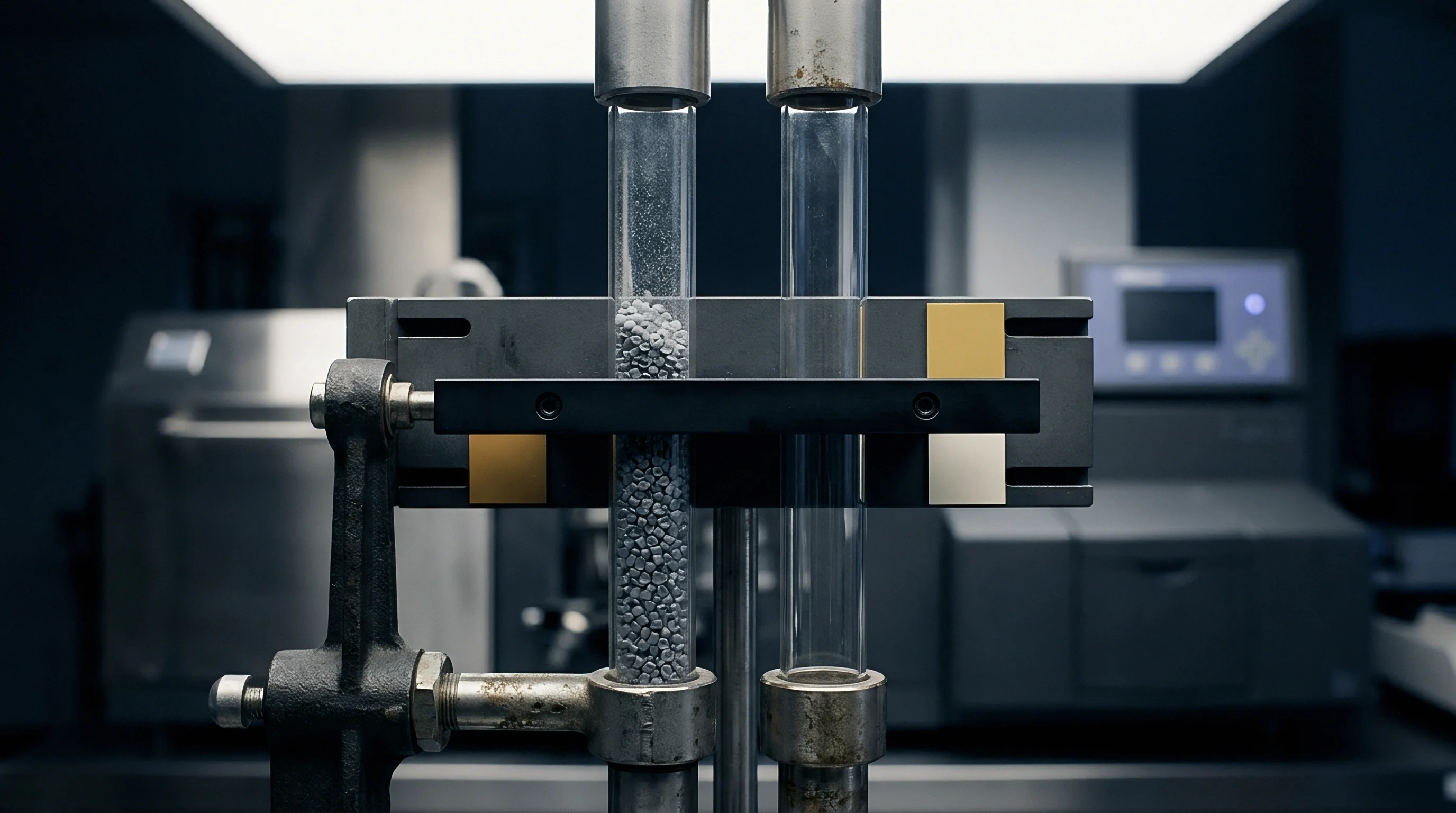

Vector
Melt flow patterns during cavity filling align short glass fibers along primary streamlines, creating directional mechanical and thermal properties in the molded component. Polymer chains and high-aspect-ratio fibers orient parallel to the velocity vector at the frozen skin, whereas shear stresses in the core generate complex tensor distributions. Glass-filled polyamides like PA66-GF30 or PA6-GF30 contract anisotropically during cooling.
Linear shrinkage parallel to flow remains low because high-modulus glass filaments restrain the matrix along their axes. Transverse to flow, the unreinforced polymer shrinks freely, yielding contraction rates three to four times higher than longitudinal values.
Secondary crystallization after ejection accentuates this anisotropy by densifying the polymer and driving further shrinkage in unreinforced matrix zones. Counteracting this, polyamide matrices absorb atmospheric moisture according to ISO 62 standards, expanding the unit cell structure over time. Because this swell occurs mainly in directions unconstrained by glass fibers, part dimensions continue to shift days or weeks after molding.
| Polymer Grade | Glass Fiber Mass Fraction (%) | Parallel Shrinkage Range (%) | Perpendicular Shrinkage Range (%) | Anisotropy Differential Ratio |
|---|---|---|---|---|
| PA6-GF15 | 15 | 0.35 – 0.55 | 0.85 – 1.15 | 2.27 : 1 |
| PA6-GF30 | 30 | 0.20 – 0.40 | 0.70 – 0.95 | 2.71 : 1 |
| PA66-GF30 | 30 | 0.15 – 0.35 | 0.65 – 0.90 | 3.00 : 1 |
| PA66-GF50 | 50 | 0.10 – 0.25 | 0.45 – 0.70 | 3.27 : 1 |
| PA12-GF30 | 30 | 0.12 – 0.30 | 0.40 – 0.65 | 2.36 : 1 |
Secondary tooling nests fail when locators treat glass-filled polyamide components as isotropic bodies. Features distant from the gate shift along non-linear vectors governed by local fiber orientation tensors rather than nominal mold shrink factors.
Gating at the heaviest wall section reduces differential orientation across thin-walled rib intersections.

Rheological Alignment and Fiber Tensor Orientation
Shear fields between cold cavity walls and the advancing melt front dictate fiber alignment through the wall thickness. Shell layers next to the mold wall freeze rapidly under high shear, locking fibers parallel to flow. The core experiences lower shear and cools more slowly, allowing fibers to tumble and align transverse to the main stream.
Consequently, thin walls develop thick, highly anisotropic skin layers, while heavier sections form larger core zones with more isotropic contraction. When secondary nests clamp components of varying wall thickness, feature positions shift along compounding angles.

Transverse Volumetric Contraction and Hydrothermal Swell
Matrix shrinkage extends long after ejection. Ejected at high temperatures, polyamide parts continue crystallizing for twenty-four hours, drifting away from theoretical cavity coordinates. As the material picks up ambient humidity toward equilibrium, moisture expansion counteracts initial thermal shrink ~ mostly across the transverse axis.
Nesting fixtures calibrated solely for immediate off-press checking fail once parts reach environmental equilibrium.
- Hole Pitch Distortions occur when variable fiber alignment between internal gates shifts pin centerline locations beyond machining tolerances.
- Planar Warp Spans arise from asymmetric skin-core fiber distribution across top and bottom mold halves, lifting primary datums off flat fixture pads.
- Perpendicular Edge Shifts develop along edges running transverse to melt flow, where unreinforced matrix contraction pulls features off nominal nest walls.
- Post-Mold Growth Binding occurs when moisture-conditioned polyamide parts swell inside rigid metal nest pockets, locking components against fixture walls.
Standard ISO plaque shrinkage values reported on material technical datasheets do not represent actual molded part geometry, as they ignore wall thickness variations and runner geometry.
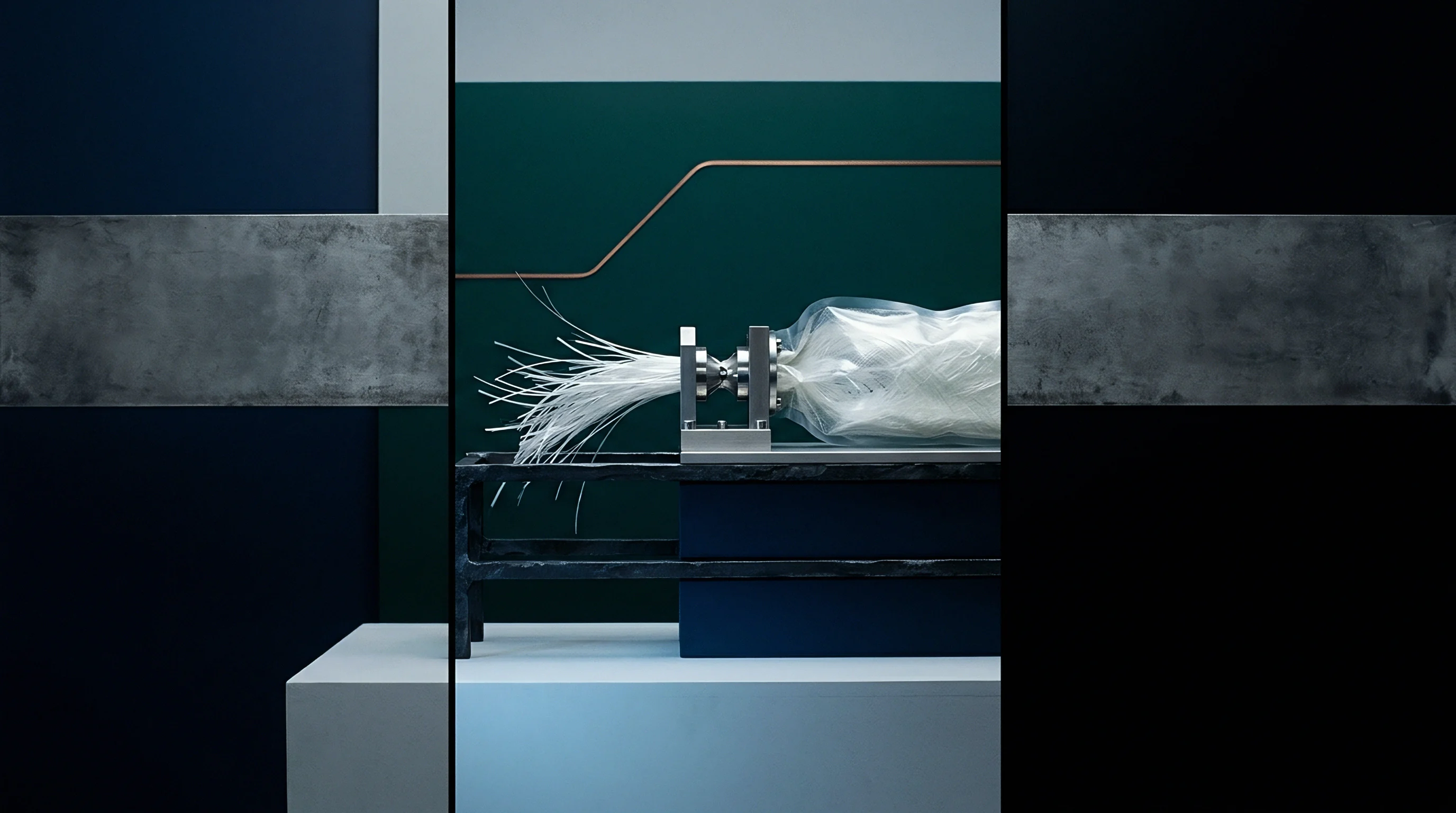
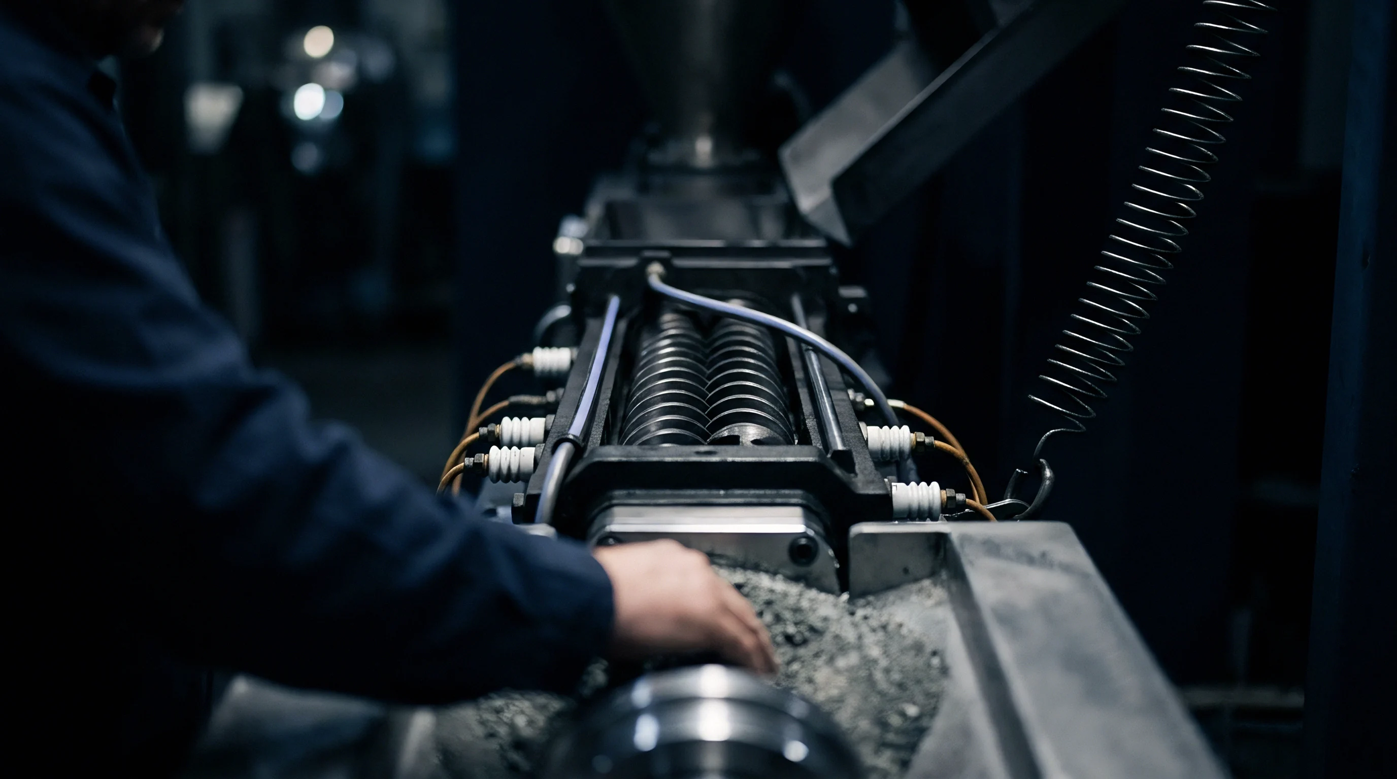
Secondary operations like multi-axis CNC milling, ultrasonic assembly, laser welding, and CMM inspection require positive mechanical positioning without forcing semi-rigid parts into temporary shapes. Tooling nests for glass-filled polyamides must use kinematic positioning strategies that accommodate baseline warpage. Clamping a warped part flat against rigid datums induces high internal stress; once clamps release post-machining, the component springs back and ruins feature tolerances.
Strict 3-2-1 datum schemes resolve spatial constraint issues on anisotropic components. Three contact points on stable features establish the primary datum, two locators along the main flow axis form the secondary datum, and a single point stops rotation. Under heavy clamping, localized contact stresses cause compressive creep in the polyamide matrix.
Furthermore, soft aluminum or unhardened steel locators wear quickly against the abrasive glass fibers exposed on molded surfaces.
Rigid clamping against a warped primary datum transfers part internal stress directly into the secondary machining cutter.

Kinematic Datum Allocation for Variable Part Geometries
Kinematic nesting layouts isolate dimensional drift by using fixed spherical contacts instead of full planar seats. Seating a warped surface on flat pads results in indeterminate multipoint contact that rocks under machining loads. Spherical buttons establish defined single-point contacts and a stable reference plane regardless of local warpage.
Similarly, hole-location schemes require diamond pins; two solid round pins in a long glass-filled part bind as soon as shrinkage alters hole spacing.
Selecting locator geometry requires analyzing local shrinkage vectors at each fixture contact interface.

Contact Stress and Surface Deflection at Locator Interfaces
Machining forces create localized contact stress at pins and nest walls. Polyamides have lower compressive yield strength than tooling metals, so unreinforced contact points deform under toggle-clamp loads. While glass-filled grades resist gross indentation, abrasive surface wear gradually opens up locator clearances over thousands of cycles.
Installing steel pads hardened to 58 HRC prevents indentation and holds datum heights stable over long runs.
- Spherical Tooling Buttons establish defined single-point primary datums on warped surfaces without inducing planar bending moments.
- Diamond Locating Pins absorb hole centerline pitch variation along primary shrinkage vectors while maintaining cross-axis location accuracy.
- Spring-Loaded Edge Pushes seat components against primary reference blocks using controlled force, preventing part deformation during secondary clamping.
- Hardened Tool Steel Wear Plates resist glass filament abrasion at high-friction insertion points, preserving fixture calibration across high unit volumes.
Locating a glass-filled component on flow-aligned features minimizes positional drift across seasonal humidity shifts.


Scale
Dimensional tolerances for molded thermoplastics follow international standards that account for material anisotropy and tool manufacturing limits. DIN 16742 assigns tolerance groups based on resin, filler content, and geometry, placing glass-filled polyamides in groups NW4 through NW9 depending on feature size and mold precision. Downstream nesting fixtures must therefore accommodate wider tolerance bands than those used for unfilled polymers, factoring in parallel shrink, transverse shrink, toolmaking tolerances, and fixture thermal expansion.
A worked example illustrates the spatial stack-up inside a machining nest. Consider a PA66-GF30 mounting bracket with a nominal 200 mm center distance between two reamed holes. The single-cavity mold is end-gated, creating a linear flow vector along that 200 mm axis.
| Parameter / Variable | Parallel Vector Axis | Transverse Vector Axis | Units |
|---|---|---|---|
| Nominal Part Dimension | 200.00 | 100.00 | mm |
| Mean Shrinkage Rate | 0.25 | 0.85 | % |
| Shrinkage Variance Band | ± 0.05 | ± 0.12 | % |
| Nominal Mold Cavity Size | 200.50 | 100.85 | mm |
| Molded Part Dimension Range (Dry As-Molded) | 199.90 to 200.10 | 99.03 to 99.27 | mm |
| Hydrothermal Expansion (50% RH Conditioned) | + 0.30 | + 0.50 | mm |
| Final Molded Part Dimension Range | 200.20 to 200.40 | 99.53 to 99.77 | mm |
| Secondary Nest Locator Pin Center Distance | 200.30 | N/A | mm |
| Required Nest Clearance per Side | 0.15 | 0.24 | mm |
| Calculations assume 7075-T6 aluminum nest plate at 23 °C reference temperature and DIN 16742 TG5 precision grade limits. | |||
Fixture locators designed around nominal part dimensions bind when parts shift to upper tolerance limits. Calculating locator placement requires stacking material shrink variation with fixture manufacturing tolerances.
A twenty-degree Celsius rise in ambient pressroom temperature expands an aluminum nest base by forty-six micrometers over a one-meter length.

Worked Construction for Nest Positioning across a Two Hundred Millimeter Span
Determining locator coordinates for the 200 mm bracket requires mapping hole center limits. Based on a nominal flow shrinkage of 0.25 percent, the longitudinal mold cavity is cut to 200.50 mm. In production, flow shrinkage varies between 0.20 and 0.30 percent with melt temperature and packing pressure changes, yielding dry as-molded hole spacings of 199.90 to 200.10 mm.
Once conditioned to standard moisture content, the component expands 0.15 percent along the flow axis, bringing hole spacing to 200.20 ~ 200.40 mm. A fixed two-pin nest machined to a nominal 200.00 mm pitch will bind. Using a fixed round pin at the primary datum and a diamond pin with ± 0.25 mm transverse float at the secondary datum accommodates this length variation without straining the part.

DIN 16742 Standard Tolerance Limits for Anisotropic Polymers
DIN 16742 Table 2 outlines dimensional tolerances for moldmaking and molding production. Industrial PA66-GF30 applications typically run under Tolerance Group TG6, which allows ± 0.53 mm variation on 100 to 200 mm dimensions. Precision molding can hit TG5, narrowing the band to ± 0.37 mm.
Designing fixed secondary nests without floating locators ignores these standard capability limits, causing high reject rates during secondary operations.
- Determine the primary melt flow direction relative to part geometry and locate major gating points from mold drawings.
- Calculate longitudinal and transverse shrink variation ranges using minimum and maximum process window bounds rather than single nominal rates.
- Establish primary, secondary, and tertiary kinematic datum points on features exhibiting the lowest directional shrinkage uncertainty.
- Calculate maximum moisture absorption dimensional swell using ISO 62 material saturation constants for the specific operating environment.
- Assign dynamic floating allowance to secondary and tertiary locator pins to absorb calculated stack-up limits.
ISO 20753 clause 4.3 mandates standard specimen geometry for shrink testing, which forces tool designers to apply empirical scaling factors when translating laboratory values into complex cavity layouts.

Relief
Handling dimensional variation in glass-filled polyamides requires compliance within the fixture itself. Dynamic locators, spring-loaded pockets, and floating datums absorb dimensional shifts while maintaining repeatable location. Solid steel pockets fail when batch variations push parts to opposite ends of the shrinkage spectrum.
Incorporating compliant or thermally matched components keeps production moving across resin lot changes.
Matching thermal expansion between the nest base and the polyamide component prevents location errors during pressroom temperature swings. Aluminum nest plates have a CTE near 23 x 10^-6 / K, compared to 11 x 10^-6 / K for tool steel. Glass-filled polyamides range from 25 to 45 x 10^-6 / K depending on orientation.
Mounting steel locators directly to an aluminum base causes pin spacing to drift as ambient temperature fluctuates across shifts.
| Substrate / Component Material | Thermal Expansion CTE (10^-6 / K) | Surface Hardness (HRC / HV) | Primary Application Role | Dimensional Compliance Mechanism |
|---|---|---|---|---|
| Tool Steel 1.2379 (D2) | 10.5 | 58 – 60 HRC | Fixed Datum Pins & Wear Pads | Zero Compliance (Rigid Base Datum) |
| Aluminum 7075-T6 | 23.4 | 150 HV | Fixture Baseplates | Matched Thermal Drift to Polyamide |
| Case Hardened Steel 1.7131 | 11.2 | 60 HRC | Guided Slide Rails | Linear Bearing Clearance Float |
| Ampco 18 Bronze | 16.2 | 200 HB | Sliding Bushings & Guides | Self-Lubricating Low-Friction Float |
Secondary nest pockets require shim packs for post-trial adjustment. Dynamic locators preserve alignment accuracy across variable thermal cycles.
DIN 16742 Table 2 Grade TG6 specifies permissible dimensional deviations for injection molded technical parts, bounding acceptable nest locator clearance.
How Does Floating Compliance Absorb Fiber Orientation Drift?
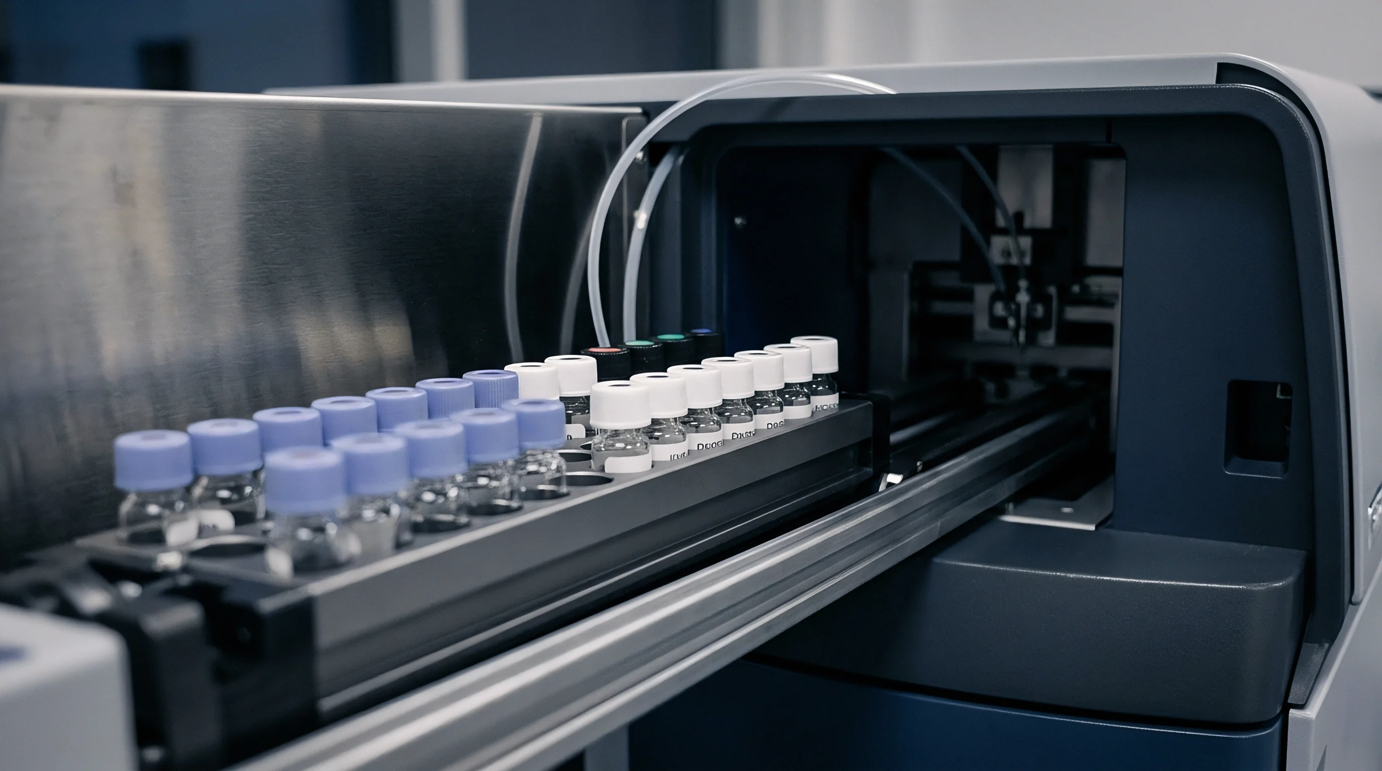
Floating pin assemblies use linear bearings or spring-centered flexures to allow motion along specific axes. A diamond pin on a cross-slide moves along the main flow axis to absorb length variations while remaining rigid transversely to preserve centerline alignment. Spring-loaded V-blocks locate round bosses regardless of volumetric shrink, centering the feature along its bisecting plane.
Flexures integrated into aluminum bases provide zero-backlash compliance, deflecting under set clamping forces and returning to neutral upon release.

Material Matching for Nest Base Substrates
Base material selection depends on the fixture’s purpose. Mounting precision locators on cast iron or tool steel creates a stable frame for CMM inspection gauges. For machining nests subject to coolant and temperature swings, an aluminum baseplate matches the CTE of the glass-filled component, minimizing thermal growth errors.
Phenolic insulation plates placed beneath the base block heat transfer from hot auxiliary equipment, preserving calibration.
- Calculated Floating Clearances defined on fixture drawings must specify allowable movement vectors matching calculated ISO 294-4 shrink bands.
- Hardened Replaceable Locators must be installed using precision dowels to allow rapid toolroom replacement when glass fiber wear exceeds tolerance limits.
- Integrated Shim Pockets must be machined behind primary reference blocks to provide two millimeters of post-trial positional adjustment.
Dynamic clamping mechanisms maintain part location accuracy across high thermal cycles without suffering spring fatigue or debris jamming.


Reserve
Fixture budgets for glass-filled polyamide components include financial provisions for post-trial machining adjustments. Initial secondary tool design relies on estimated shrinkage values provided by resin suppliers or Moldflow tensor simulations. Actual cavity flow dynamics, gate freeze times, and batch-to-batch polymer viscosity variations produce real-world part geometries that deviate from initial solid models.
Cutting secondary nest pockets to final drawing dimensions prior to evaluating first-shot moldings leads to scrap tooling.
Tooling quotes for secondary nests usually tie payment milestones to sample approval gates. Standard contracts follow a metal-safe approach ~ machining pockets slightly undersized and pin positions conservative so final EDM or CNC recutting can occur after T1 sample evaluation. Allocating fifteen to twenty percent of the fixture budget for post-trial adjustments prevents cost overruns when real-world shrinkage diverges from predictions.

Commercial Provisioning for Secondary Fixture Modification
Fixture development contracts routinely include dedicated allowances for post-mold adjustment hours. Toolmakers construct nests using modular insert pockets rather than solid monoblock bases. Removable hardened inserts permit fast wire-EDM modifications without recutting the whole fixture.
If shrinkage forces a shift in locator coordinates, recutting a modular insert costs a fraction of rebuilding the entire nest assembly. RFQ specifications should mandate modular inserts at all primary datums.

Sign-Off Protocols and Verification Benchmarks
Fixture sign-off requires statistical capability verification using production-grade parts. Qualifying a nest with prototype parts, unreinforced resins, or trial material lots produces meaningless metrics. Final acceptance demands evaluating fifty consecutive molded parts from a steady-state production run.
Across this sampling, the fixture must support Cpk values above 1.67 for all secondary features under normal pressroom conditions.
Ignoring anisotropic shrinkage during early nest design leads directly to premature locator wear, out-of-spec machined features, and unexpected tooling rework costs before production approval.