Electroformed Copper Inserts for Millimeter-Wave Tool Steel Tooling Assemblies
Electroformed copper inserts enable sub-30nm surface roughness and 35% faster cycle times in mmWave tooling when thermal expansion gaps are engineered.
Bath
Metal deposition onto reusable or sacrificial mandrels establishes the foundational geometry for millimeter-wave cavity inserts. High-frequency RF components operating at 77 to 81 gigahertz demand cavity surface roughness values below thirty nanometers Ra. Conventional five-axis CNC micromilling leaves tool feed marks and cutter radius artifacts that distort electromagnetic wave propagation. Acid copper electroforming deposits atomic layer upon atomic layer of pure copper directly onto a precision-machined or photo-lithographically defined mandrel, replicating sub-micron surface contours with extreme fidelity.
Mandrels require precise handling. Aluminum alloys such as 6061-T6 serve as standard sacrificial mandrel materials because hot concentrated sodium hydroxide solutions dissolve the aluminum without attacking the electrodeposited copper shell. Stainless steel grade 316L or passivated nickel mandrels provide reusable options when cavity draft angles exceed one degree, permitting mechanical separation without chemical dissolution.
The selection between sacrificial and permanent mandrels dictates early tooling expenditure and insert edge definition.

Mandrel Selection and Sacrificial Substrate Mechanics
Mandrel manufacturing determines the initial micro-geometry of the electroformed shell. Machining aluminum mandrels with single-crystal diamond tools produces surface finishes below ten nanometers Ra, which transfer directly to the interior copper cavity wall. Chemical dissolution of aluminum mandrels proceeds in a twenty percent sodium hydroxide solution held at sixty degrees Celsius.
Dissolution rates range from zero point five to one point zero millimeters per hour. Etching bath agitation prevents localized hydrogen gas accumulation, which creates pitting on the internal copper micro-structures if gas bubbles adhere to the metal surface during stripping.
Permanent mandrels require passivation to facilitate part release. Passivation forms a thin, stable chromium oxide layer on stainless steel surfaces, reducing adhesion between the substrate and the deposited copper layer. Insufficient oxide density causes mechanical galling during insert separation, destroying sub-micron waveguide features.
Excessive oxide thickness creates electrical insulation spots that trigger localized current concentration, producing non-uniform plating thickness across micro-channel features.

Acid Sulfate Electrolyte Chemistry and Grain Refinement
Standard electroforming baths rely on acid copper sulfate chemistry. A representative bath contains two hundred grams per liter of copper sulfate pentahydrate and sixty grams per liter of sulfuric acid. Chloride ions maintained between seventy and ninety milligrams per liter promote uniform anode dissolution and aid brightener activation.
Electrodeposition occurs at current densities between one point five and three point zero amperes per square decimeter, producing a copper growth rate of eighteen to thirty-six micrometers per hour.
Deposition at two amperes per square decimeter yields a micro-hardness of 140 Vickers when chloride concentration stays between seventy and ninety milligrams per liter.
Organic levelling additives alter grain orientation during electrodeposition. Polyethylene glycol and sulfur-containing aliphatic compounds suppress growth on high-current-density projection points while accelerating deposition in micro-grooves. Controlled addition of grain refiners reduces the crystallite size of the deposited copper from five micrometers down to three hundred nanometers.
Fine grain structures elevate as-deposited micro-hardness from eighty Vickers up to one hundred sixty Vickers, increasing resistance to mechanical deformation during subsequent tool assembly operations.
| Chemical Component / Parameter | Acid Sulfate Formulation | Pyrophosphate Formulation | Mechanical Impact on Insert |
|---|---|---|---|
| Copper Metal Content | 45 – 55 g/L | 22 – 30 g/L | Controls maximum sustainable plating current density |
| Free Acid / Complexing Agent | 50 – 70 g/L H2SO4 | 150 – 200 g/L K4P2O7 | Determines bath electrical conductivity and throwing power |
| Chloride Ion Concentration | 70 – 90 mg/L | None (Inhibits plating) | Prevents anode passivation and smooths cathode deposit |
| Operating Bath Temperature | 25 – 32 °C | 50 – 55 °C | Influences grain size growth and thermal stress buildup |
| As-Deposited Hardness | 120 – 160 HV | 180 – 220 HV | Dictates wear life under cyclic plastic melt pressures |
Platers frequently claim that microscopic surface nodules stem entirely from airborne dust rather than organic brightener breakdown products in the electrolyte.

Geometry
Sub-micron feature fidelity decides electromagnetic performance in injection-moulded dielectric waveguides and radar antenna housings operating above thirty gigahertz. At millimeter-wave frequencies, electrical currents flow within a micro-thin outer skin of the conductor material. High surface roughness increases the effective path length of the radio frequency current, generating significant signal attenuation and phase distortion.
Electroformed copper inserts reproduce mandrel topography with nanometer precision, eliminating physical machining steps inside small waveguide channels.
Surface finish dictates signal loss. For a 77 gigahertz signal travelling along a copper conductor, the skin depth measures approximately two hundred thirty-eight nanometers. Effective cavity conduction requires an internal surface roughness Ra lower than one-third of the skin depth.
Achieving a surface finish below eighty nanometers Ra via physical metal cutting inside micro-pockets measuring less than two millimeters wide remains extremely difficult with mechanical end mills. Electroforming circumvents cutter access limitations by depositing metal around the outside of an accessible male mandrel.

Electromagnetic Skin Depth and Surface Micro-Roughness Limits
Conductor attenuation scales non-linearly with relative surface roughness. When RMS surface roughness Rq approaches or exceeds skin depth, conductor losses increase by up to sixty percent compared to an ideal smooth surface. Electroformed copper shells created from polished glass or silicon mandrels hold surface roughness values below fifteen nanometers Ra. Polymer parts moulded within these cavities mirror this micro-smooth surface, yielding low insertion losses when coated with conductive metallization layers in post-processing steps.
Draft angle requirements in micro-moulded dielectric waveguide channels differ from standard injection moulding specifications. Shallow draft angles down to zero point two five degrees become workable due to the exceptionally high surface finish of electroformed cavities. Low surface roughness reduces sliding friction during ejection, preventing part distortion even when stripping long, parallel dielectric channel features from the steel assembly.

Micro-Channel Cavity Replication and Corner Radius Limits
Internal corner radii limit high-frequency waveguide performance. Mechanical milling tools leave an internal corner radius governed by the cutting tool radius, typically no smaller than zero point two millimeters for micro-endmills. Electroforming replicates sharp male mandrel edges down to corner radii smaller than two micrometers.
Sharp corner definition ensures precise propagation of higher-order electromagnetic modes inside molded radar horn structures.
Shrinkage compensation must be calculated directly into the mandrel geometry. Cyclic Olefin Copolymers processed at mold temperatures of one hundred twenty degrees Celsius exhibit volumetric shrinkage rates between zero point four percent and zero point seven percent. Liquid Crystal Polymers display highly anisotropic shrinkage, showing zero point one percent shrinkage parallel to the melt flow direction and up to zero point six percent transverse to flow.
Mandrel wire EDM procedures account for these directional polymer shrinkage vectors prior to electrodeposition.
- Skin effect conductor attenuation occurs when wall surface roughness exceeds skin depth, forcing electrical current into longer physical paths along micro-peaks and valleys.
- Dimensional cavity distortion arises from non-uniform electrodeposition rates at sharp internal corners where electrical current concentration accelerates local metal growth.
- Parting line flash generation develops when corner radii on insert edges round off under high injection pressure due to improper backup plate compression.
- Ejection shear scuffing damages optical-grade cavity walls when draft angles fall below target thresholds or ejector pin timing shifts out of balance.
Sharp internal cavity corners always require reduced current deposition rates to prevent preferential ion growth from building localized stress points.

Interface
Tool steel pockets surrounding electroformed copper shells absorb substantial thermal expansion differentials during mold bring-up. Pure copper exhibits a coefficient of thermal expansion of sixteen point five multiplied by ten to the power of minus six per Kelvin. AISI 420 stainless steel and DIN 1.2083 tool steel present coefficients of thermal expansion between ten point five and eleven point eight multiplied by ten to the power of minus six per Kelvin.
Heating the tooling assembly from ambient shop temperatures to an operating mold temperature of one hundred thirty degrees Celsius causes the copper insert to expand significantly more than the surrounding steel pocket.
Pocket clearances drive alignment. An unconstrained copper insert measuring sixty millimeters across expands by zero point one zero nine millimeters when heated across a temperature delta of one hundred ten degrees Celsius. The surrounding steel pocket expands by only zero point zero seven two millimeters over the same temperature rise.
This differential expansion produces thirty-seven micrometers of interference, generating intense compressive stresses inside the copper insert if mechanical clearance allowances are omitted from tool drawings.

Thermal Expansion Mismatch and Pocket Fit Allowances
Engineered pocket clearances prevent physical buckling of thin-walled electroformed inserts. Machining steel receiving pockets to an ISO 286 clearance fit grade such as H7/g6 establishes an initial lateral gap of twelve to twenty-eight micrometers at twenty degrees Celsius. As the mold reaches operational equilibrium at one hundred twenty degrees Celsius, thermal expansion closes this clearance, creating a firm interference fit without exceeding the yield strength of the electroformed copper.
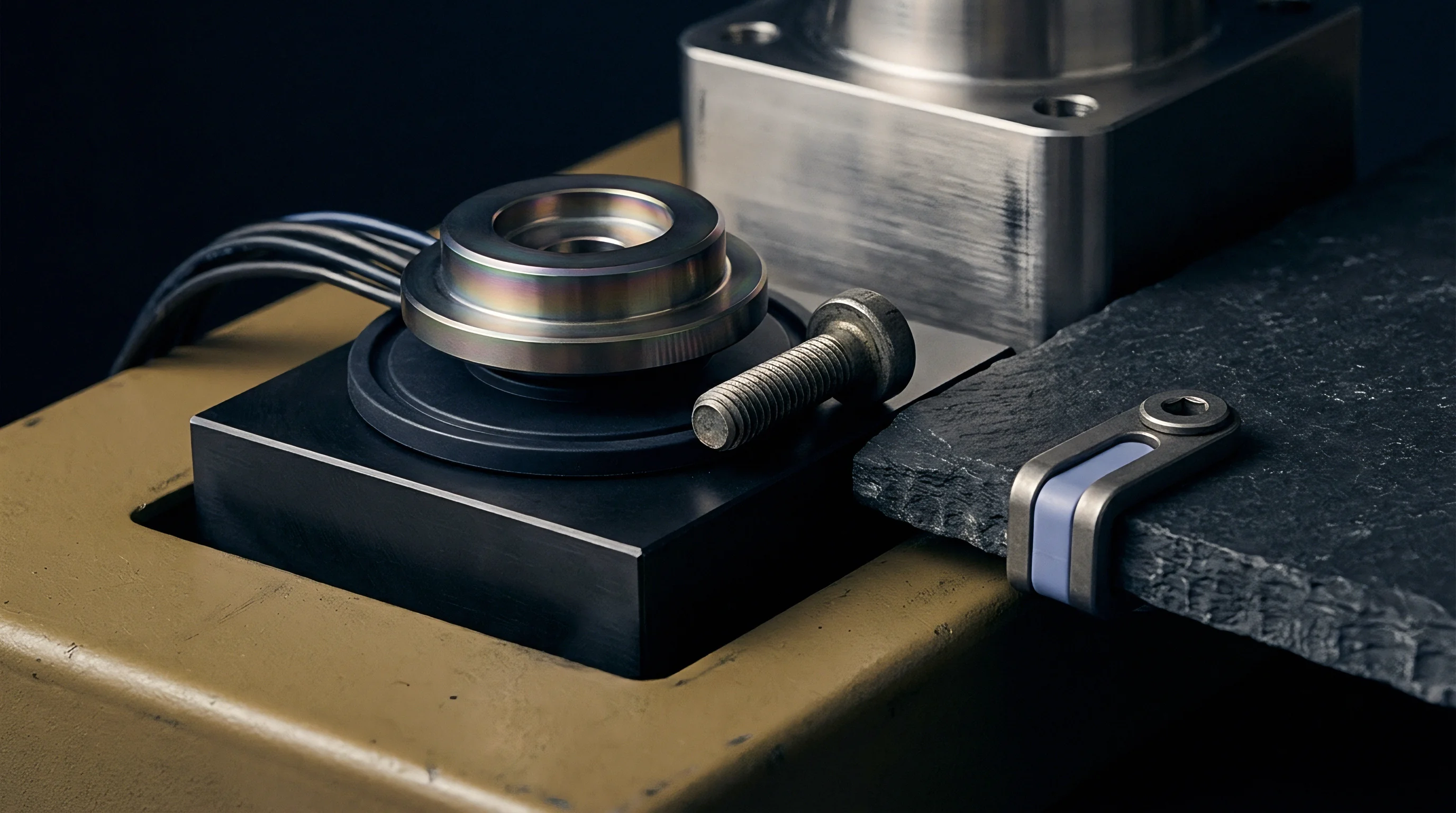
Clamping force limits movement. Direct steel clamping plates hold the copper shell inside the receiver pocket. Incorporating compliant beryllium-copper shim plates or high-density graphite sheets beneath the insert base accommodates vertical thermal expansion while maintaining uniform contact pressure across the rear face of the shell.

How Does Pocket Clamping Mechanics Prevent Shell Deformation?
Dynamic compression during the injection phase requires rigid backing. Pure electroformed copper possesses a modulus of elasticity of one hundred ten gigapascals, compared to two hundred ten gigapascals for hardened tool steel. Under injection pressures exceeding one thousand bar, an unbacked electroformed shell undergoes elastic deformation, causing cavity dimension drift and wall deflection beyond sub-micron tolerance thresholds.
Clearance fits defined under ISO 286 H7 and g6 cause insert fretting and thermal isolation when operational temperature shifts exceed eighty degrees Celsius.
Backing materials restore structural stiffness. Backing options include casting low-shrinkage epoxy filled with aluminum powder behind the copper shell or machining precision copper-tungsten alloy support blocks. High-conductivity copper-tungsten alloys with seventy percent tungsten content exhibit a low thermal expansion coefficient of eight point five multiplied by ten to the power of minus six per Kelvin while maintaining a high elastic modulus of two hundred seventy gigapascals, providing rigid support against peak injection packing loads.
| Material Designation | Thermal Conductivity (W/m·K) | Coefficient of Thermal Expansion (10⁻⁶/K) | Elastic Modulus (GPa) | Yield Strength (MPa) |
|---|---|---|---|---|
| Electroformed Pure Copper | 380 – 395 | 16.5 – 16.8 | 110 – 120 | 140 – 220 |
| DIN 1.2083 (AISI 420) Steel | 24 – 26 | 10.5 – 11.2 | 215 | 1450 (Hardened) |
| DIN 1.2343 (AISI H13) Steel | 28 – 30 | 11.5 – 12.0 | 210 | 1600 (Hardened) |
| Copper-Tungsten (W70-Cu30) | 180 – 200 | 8.3 – 9.0 | 270 – 290 | 650 |
| Beryllium Copper (C17200) | 105 – 130 | 17.0 – 17.8 | 130 | 960 – 1200 |
Improper clamping clearance transforms precision cavity alignment into permanent steel pocket deformation after the first production cycle.

Window
Process repeatability for millimeter-wave components depends on thermal stabilization across the high-conductivity copper cavity insert. Pure electroformed copper transfers heat at rates exceeding three hundred eighty Watts per meter-Kelvin, representing a fifteen-fold increase over conventional stainless tool steel. Rapid thermal diffusion flattens temperature gradients across the mold surface, preventing localized hot spots that trigger non-uniform polymer cooling and differential part warpage.
Thermal conductivity speeds cooling. High heat dissipation shortens polymer solidification times during the injection cycle. In thin-walled antenna radome applications, cooling time accounts for over sixty percent of total cycle duration.
Replacing steel cavities with electroformed copper inserts reduces cooling hold time from twelve seconds down to four point five seconds, increasing overall press output without compromising dimensional stability.

Thermal Dynamics and Cycle Time Compression
Melt crystallization behavior stabilizes under uniform cavity cooling rates. Cyclic Olefin Copolymers such as Topas 5013L require tight temperature control during the filling and packing phases to avoid residual optical birefringence and localized density shifts. Electroformed copper cavities hold surface temperatures within plus or minus zero point eight degrees Celsius across the entire cavity plane, whereas tool steel cavities under identical coolant flow conditions display thermal variations exceeding plus or minus four point five degrees Celsius.
Melt pressure distorts shell structures if backing isolation occurs. Integrating piezoresistive pressure sensors directly behind the backup plate measures real-time force transmission through the copper shell during injection. Rapid pressure pulse feedback allows press programmers to tune pack-and-hold profiles, preventing cavity over-pressurization that leads to parting-line flashing or copper yield deformation.
Polymer Melt Rheology in Micro-Structured Copper Cavities
To establish a stable production window when bringing up a tool containing electroformed copper inserts, operators follow a strict sequence of thermal and mechanical verification steps.
- Mount the insert assembly into the steel receiver plate and verify flat seating with feeler gauges.
- Torque retention screws sequentially to twelve newton meters in a cross pattern.
- Pre-heat mold circuits to one hundred twenty degrees Celsius for sixty minutes.
- Measure pocket expansion with dial indicators before introducing polymer melt.
- Run ten initial purge cycles to establish stable thermal equilibrium.
Higher mold surface conductivity eliminates localized hot spots and stabilizes polymer crystallization across thin dielectric walls.
Viscosity behavior in micro-channels dictates higher melt temperatures. LCP resins flow through micro-waveguide channels measuring zero point three millimeters wide only when wall temperatures stay near the polymer melting point. The rapid thermal transfer of copper inserts allows elevated mold surface temperatures during injection followed by rapid chilling during the cooling phase, extending spiral flow length by up to twenty-eight percent compared to standard steel tooling options.
Cavity pressure sensors placed directly behind the copper backup plate provide immediate feedback on melt front progression, allowing press operators to adjust pack pressure before thermal gradients disturb part dimensions.
Drift
Metallurgical soft spots develop within electrodeposited copper structures subjected to sustained high-temperature moulding conditions. As-deposited electroformed copper exhibits grain refinement induced by organic bath additives, producing micro-hardness values up to one hundred sixty Vickers. Repeated thermal exposure to molten polymers at temperatures between two hundred eighty and three hundred forty degrees Celsius triggers recrystallization and grain growth inside the copper lattice.
Copper yields under stress. Grain growth reduces material hardness down to forty-five to sixty Vickers after extended operational cycles. Softened copper inserts suffer plastic deformation around gate regions and parting lines, where localized melt impact forces and high clamping loads exceed the degraded yield strength of the metal.

Recrystallization Kinetics and Micro-Hardness Loss
Recrystallization kinetics accelerate as operating temperatures approach half the absolute melting temperature of copper. Continuous molding with LCP resins at continuous tool wall temperatures of one hundred sixty degrees Celsius causes measurable micro-hardness drops within twenty thousand press cycles. Microstructural analysis reveals coarsening grain boundaries that reduce atomic dislocation resistance, causing subtle dimension shifts in critical millimeter-wave waveguide channels.
Fretting destroys insert seats. Micro-motion between the softened copper shell and the hard steel receiver pocket wears away the lower support interface during repeated injection pressure spikes. Material loss at the rear seating face allows the insert to push back under injection load, generating flash at the part perimeter and destroying dimensional repeatability.

Abrasive Polymer Wear and Cavity Life Limits
Mineral and glass-filled polymers cause rapid mechanical erosion of unplated copper surfaces. A thirty percent glass-fiber reinforced LCP resin acts as an abrasive slurry when injected through narrow gate passages at velocities exceeding fifty meters per second. Erosion strikes gate entrance radii and flow deflection corners first, rounding off sharp RF impedance-matching steps within five thousand shots.
Electrodeposited copper inserts exposed to temperatures above two hundred degrees Celsius undergo rapid recrystallization that reduces yield strength by half within fifty operating hours.
Hard coatings alter dimensions. Surface plating with thin electrodeposited nickel-cobalt alloys or Physical Vapor Deposition coatings extends insert wear life. A three-micrometer layer of NiCo alloy provides a surface hardness of five hundred50 Vickers, shielding the underlying high-conductivity copper against abrasive polymer wear.
Coating thickness must be factored into original mandrel dimensions to avoid altering final cavity geometry.
Tool designers continue to debate whether thin nickel-cobalt capping layers alter high-frequency conductor attenuation profiles sufficiently to offset their significant resistance to abrasive polymer wear.
Amortisation
Capital allocation decisions for high-frequency antenna manufacturing hinge on comparing electroformed insert replacement schedules against direct steel CNC machining costs. A four-cavity steel tool cut from hardened 1.2083 stainless steel requires five-axis micro-milling and sinker EDM steps costing eighty-five thousand dollars. Steel cavities survive two hundred fifty thousand production cycles without refurbishment, but run at an average cycle time of twenty-two seconds due to limited thermal conductivity.
Cycle times drop significantly. An equivalent tool assembly utilizing a steel receiver frame with four electroformed copper inserts requires an initial master mandrel and insert tooling spend of forty thousand dollars. Due to copper’s high heat transfer efficiency, the injection cycle drops from twenty-two seconds down to fourteen seconds, cutting press time by thirty-six percent across the production run.

Tooling Expenditure Breakdown and Mandrel Amortization Calculations
Insert wear requires scheduled replacement budgeting. Electroformed copper inserts exposed to unfilled COC resin require cavity replacement every eighty thousand cycles due to parting-line fatigue and thermal soft spots. Replacement copper insert sets cost eleven thousand two hundred dollars per four-cavity set, using the original master mandrels stored in climate-controlled toolroom storage.
Financial evaluation across a total production volume of two hundred fifty thousand units demonstrates the economic trade-offs between initial steel cut tooling and modular electroformed copper inserts.
| Cost Component / Parameter | Direct Steel Cavity Tooling | Electroformed Copper Insert Assembly |
|---|---|---|
| Initial Master Mandrel Fabrication | $0 (Not required) | $22,000 (One-time cost) |
| Initial Tooling / Insert Fabrication | $85,000 | $18,000 (Set of 4 inserts) |
| Total Initial Tooling Investment | $85,000 | $40,000 |
| Expected Cavity Service Life | 250,000 shots | 80,000 shots per set |
| Insert Refurbishment / Replacement Spent | $0 | $22,400 (2 replacement sets) |
| Total Tooling Capital Spent (250k Units) | $85,000 | $62,400 |
| Moulding Cycle Time (77 GHz Radome) | 22.0 seconds | 14.0 seconds |
| Machine Hours required for 250k Parts | 1,527.7 hours | 972.2 hours |
| Press Operating Cost at $65/Hour | $99,300 | $63,190 |
| Combined Tooling & Press Cost (250k Volume) | $184,300 | $125,590 |

Landed Part Economics and Replacement Cycle Thresholds
Machine time savings outweigh insert maintenance expenses. Operating a ninety-tonne electric press costs sixty-five dollars per hour. Saving eight seconds per cycle across two hundred fifty thousand parts reduces press runtime by five hundred fifty-five point five hours, generating thirty-six thousand one hundred ten dollars in direct machine cost reductions.
Net overall savings exceed fifty-eight thousand dollars over the project lifecycle.
Tooling decisions govern margins. Procurement managers verify technical requirements before committing capital to mandrel electroforming programs.
- Frequency threshold verification confirms whether surface roughness requirements strictly mandate electroformed micro-cavity replication over mechanical milling options.
- Thermal cooling payback calculation weighs machine-hour cost savings against expected insert replacement intervals over total lot volume forecasts.
- Steel pocket modularity design ensures insert changing takes less than two press hours without removing the main mold base from the machine.
- Spare insert stocking policy buffers production against unexpected cavity parting-line damage or abrasive gate erosion during high-volume runs.
Including DIN 16742 Molded Part Tolerance Group TG3 compliance clauses into insert procurement contracts transfers the financial burden of cavity thermal drift rework back to the tool maker.