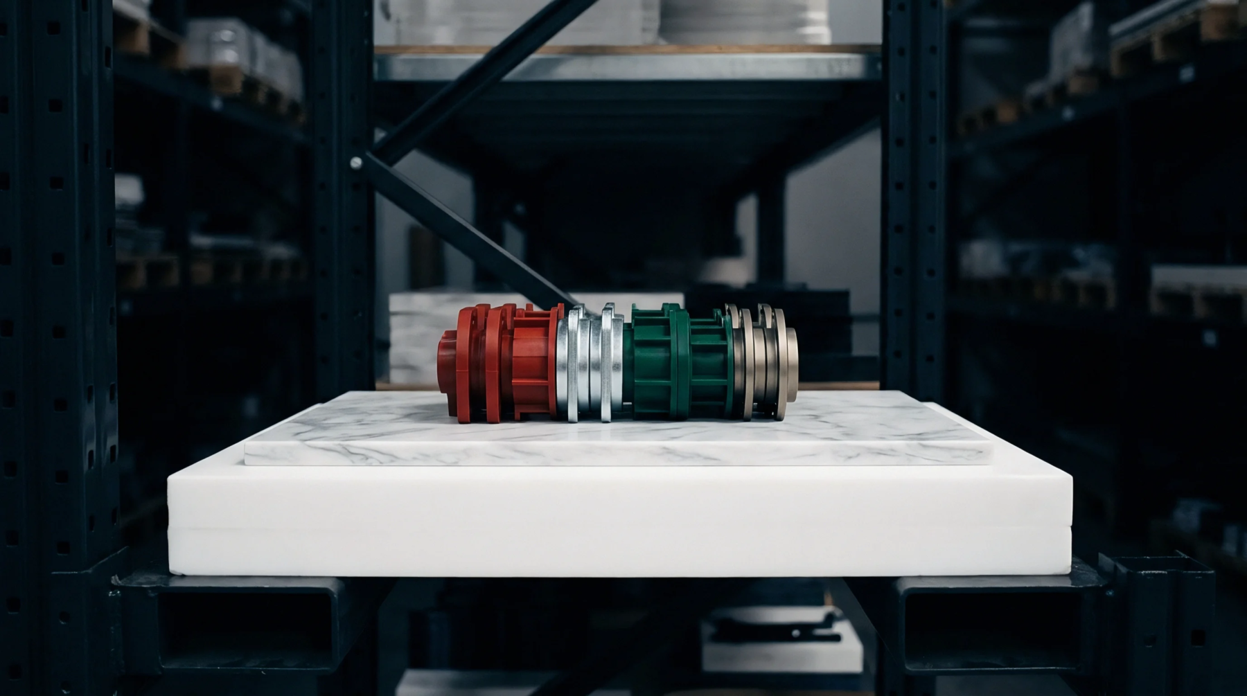
Electroformed Copper Inserts for Millimeter-Wave Tool Steel Tooling Assemblies
Electroformed copper inserts enable sub-30nm surface roughness and 35% faster cycle times in mmWave tooling when thermal expansion gaps are engineered.
Mechanical pairing dimensions in tooling design govern the allowable dimensional gap between mating components to ensure relative motion without binding or excessive play. In mould construction, a clearance fit dictates the operational space between ejector pins, leader pins, sliding cores, and their corresponding guide holes. The fit ensures that moving steel members slide freely under severe thermal expansion cycles while preventing pressurized molten polymer from creeping into the interface.
Diametral clearances for sliding tool actions typically range from six to twenty micrometres depending on pin diameter and working temperature. The boundary of this dimensional fit ends at static insert pockets, where interference or transitional fits take over to eliminate mechanical displacement entirely.
Free mechanical travel of moving mould components prevents catastrophic galling during continuous press operation. Specifying a clearance fit on ejector pins ensures reliable forward stroke and spring return without mechanical seizure inside the ejector plate bushings. Thermal expansion from mould heating reduces initial assembly gaps, requiring designers to calculate operating clearances at working tool temperatures rather than room temperature.
Uneven tool heating narrows these gaps unpredictably, stalling ejector plates and triggering emergency press stops. Hardened coatings like diamond-like carbon or titanium nitride maintain low friction within the sliding gap. Regular maintenance protocols mandate periodic lubrication to wash out microscopic metal fines generated across millions of production cycles.
Polymer melt viscosity determines the maximum permissible dimensional gap at parting lines and sliding interfaces before resin enters the clearance space. High-flow materials such as liquid crystal polymers or unreinforced polyamides flash into openings as small as ten micrometres under standard injection pressures. When a clearance fit allows excessive space between an ejector pin and its through-hole, the advancing melt front forces thin resin collars around the pin head.
Part specifications mandate clean aesthetic surfaces without flash rings, forcing moulders to trim ejected parts manually or replace worn tooling components. Regrind polymers worsen flash tendencies when degraded molecular chains lower effective melt viscosity during the high-pressure filling phase. Tool designers consequently balance the clearance needed for sliding motion against the critical flash threshold of the specified polymer grade.
Repetitive mechanical cycling gradually enlarges the bore diameter of guiding bushings while wearing down outer pin circumferences. Ejector pin heads develop lateral slop that leads to pin bending during rapid forward ejection strokes. As the internal gap widens beyond original design limits, plastic ingress accelerates mechanical abrasion by acting as a grinding medium within the slide channel.
Costly secondary operations arise when flash on aesthetic part surfaces exceeds drawing allowances, forcing unplanned tool teardowns. Tool shops measure pin clearance using calibrated plug gauges during regular mold audits to catch worn holes before cavity steel sustains permanent damage. Refurbishing worn holes involves reaming the bore oversize and fitting matched custom pins to restore original operating clearances.
Electroformed copper inserts enable sub-30nm surface roughness and 35% faster cycle times in mmWave tooling when thermal expansion gaps are engineered.
Expertise is a utility, not a secret. sentiention™ publishes its working knowledge as open reference: intelligence layer covering the materials it sources, the markets it enters, and the reference that serves both.