Acoustic Propagation Velocity Tracking in High Cavitation Moulding Tools
Tracking ultrasonic propagation velocity across high cavitation tools provides real-time density, fill balance, and gate seal control without part marking.

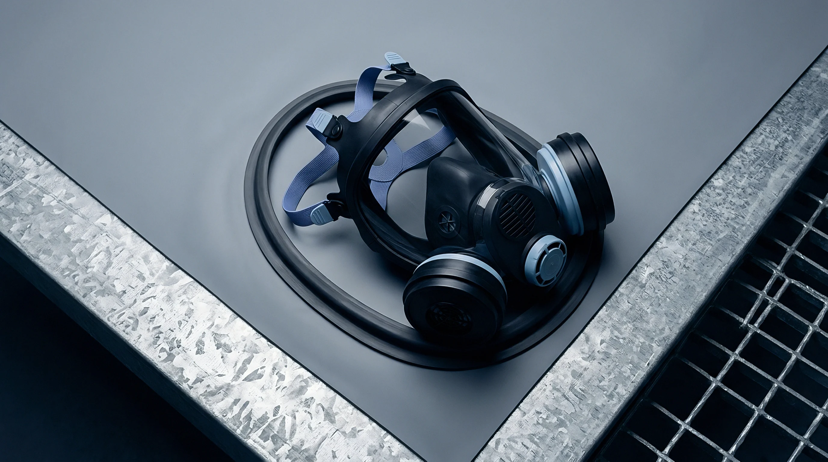
Echo
A piezoelectric pulse launched through hardened P20 tool steel enters the cavity at the exact instant polymer melt contacts the cavity steel. High cavitation injection tools, operating 32 to 128 cavities on cycle times under four seconds, present severe acoustic measurement challenges. Ultrasonic waves pass through multi-layer steel assemblies, across fluid interfaces, and into a non-isothermal polymer body undergoing rapid shear and crystallization.
Longitudinal wave velocity tracks the thermodynamic state of the polymer melt in real time. The acoustic propagation speed correlates directly with local melt density and bulk modulus through the Laplace-Newton relation, where sound velocity equals the square root of bulk modulus divided by density.
Process control in multi-cavity tooling relies on precise transit time detection. When molten resin fills a mold cavity, the contact between polymer and steel transforms an acoustically open boundary into a transmitting interface. High frequency transducers, operating between two megahertz and ten megahertz, transmit longitudinal ultrasonic pulses through the cavity wall.
As the polymer phase transitions from an amorphous melt into a constrained solid, sound velocity shifts by several hundred meters per second. Tracking this phase shift provides immediate feedback on melt front position, cavity fill balance, packing state, and gate seal timing across all cavities simultaneously.

Ultrasonic Wave Dynamics in Polymeric Phase Transitions
A piezoelectric pulse launched through hardened P20 tool steel enters the cavity at the exact instant polymer melt contacts the cavity steel. Steel temperature influences acoustic velocity. In liquid semi-crystalline polymers like polypropylene or high density polyethylene, sound velocity ranges between 950 and 1150 meters per second at melt temperatures above 200 degrees Celsius.
As cooling proceeds and crystallization begins, local density increases alongside an abrupt rise in bulk modulus. Sound velocity escalates rapidly, reaching 1800 to 2200 meters per second in the solid state at room temperature. Amorphous polymers such as polycarbonate and polymethyl methacrylate display a smoother, continuous velocity elevation through the glass transition zone without the sharp discontinuity characteristic of semi-crystalline resins.
Wave attenuation accompanies velocity change during the injection cycle. In molten polymer, high shear rates and viscous dissipation absorb acoustic energy, reducing peak amplitude. As the melt freezes against cold tool cavity walls, acoustic attenuation drops dramatically, allowing higher amplitude reflections to return to the sensor.
Sensor positioning determines signal resolution. Positioned directly opposite a cavity pin or ejector face, a single transducer captures both transit time through the steel thickness and round-trip propagation across the polymer wall thickness. Calculating acoustic velocity requires accurate wall thickness tracking, taking thermal contraction and mold deflection into account.
A high frequency ultrasonic pulse traverses molten polymer at velocity rates governed strictly by material bulk modulus and density.

Transmission Time Calculations across Cavity Boundaries
A longitudinal sound pulse travels at approximately 5900 meters per second through tool steel before encountering the liquid polymer layer. Interfacial reflection coefficients govern the fraction of acoustic energy transmitted into the polymer cavity. The acoustic impedance of tool steel, approximately 45 mega-Rayls, far exceeds the acoustic impedance of molten polymer, which averages between 1.2 and 1.8 mega-Rayls.
This extreme impedance contrast causes over ninety percent of the acoustic energy to reflect at the steel-polymer interface during early injection. Only a minor fraction penetrates the melt, requiring high gain low noise signal amplification to process the returning echo.
Determining ultrasonic transit time across the polymer thickness uses cross-correlation algorithms or threshold peak detection. The total transit time measured by press-side electronics incorporates fixed steel propagation delays and dynamic polymer propagation delays. Calibrating the signal baseline requires subtracting the steel transit time from the total delay time according to a defined procedure.
- Calibrate piezoelectric signal baseline by pulsing sound waves through dry, closed mold cavities prior to melt injection.
- Record ultrasonic travel time through empty mold cavity steel to isolate fixed steel path acoustic delays.
- Measure signal delay across polymer melt front arrival when molten resin bridges the mold cavity steel interface.
- Compute sound propagation velocity across melt thickness using real-time cavity wall contraction corrections.
- Map velocity shift curve against cavity pressure profile to establish baseline acoustic signatures for balanced filling.
Tool suppliers often assert that conventional cavity pressure sensors render ultrasonic tracking redundant, ignoring the fact that pressure transducers fail to register core solidification states after gate seal occurs.


Viscosity
Thermal gradients within high cavitation tools induce severe viscosity variations across individual impression channels. Polymer melt viscosity directly affects acoustic wave propagation velocity through its coupling with melt compressibility and specific volume. Higher melt viscosity corresponds to increased molecular chain entanglement, elevated flow resistance, and altered bulk elasticity under pressure.
When processing resin lots with varying melt flow indexes, acoustic tracking detects batch-to-batch polymer variations instantly press-side. High viscosity melt resists packing compression, altering the acoustic velocity growth curve during the holding phase.
Pressure changes inside the cavity compress the molten polymer, increasing density and bulk modulus simultaneously. Pressure elevates bulk modulus. During the filling phase, cavity pressure rises from ambient to several hundred bar, causing longitudinal sound velocity to rise linearly with pressure.
Ultrasonic tracking measures this pressure dependence, providing an optical-free, non-destructive probe of internal thermodynamic conditions without placing intrusive sensor pins directly on cosmetic component surfaces.

Melt Compressibility and Sound Speed Dependency
The bulk modulus of a semi-crystalline resin increases abruptly as hydrostatic pressure builds during the packing phase. Sound propagation velocity scales with hydrostatic pressure at rates between 0.85 and 1.45 meters per second per bar, depending on polymer morphology and melt temperature. At low cavity pressure, acoustic velocity remains sensitive to melt temperature changes, dropping approximately 2.5 to 4.1 meters per second for every degree Celsius increase in melt temperature.
Tracking sound speed across the packing phase isolates the pressure effect from the thermal cooling effect, exposing real-time density development within the mold.
Void formation dampens sound waves. Inadequate packing pressure creates micro-voids or sink marks within thick part sections, dropping local bulk modulus to zero and causing severe scattering of the ultrasonic pulse. When micro-voids appear, acoustic signal amplitude drops below detection thresholds, triggering immediate part rejection signals before ejection occurs.
Acoustic tracking thus acts as a direct inspector of internal volumetric integrity.

Thermal Gradient Tracking during Solidification
Cooling water flowing through conformal channels extracts thermal energy from the outer polymer skin toward the core layer. Thermal dissipation varies by cavity. The formation of a frozen outer layer creates a steep sound velocity profile across the part cross-section.
Ultrasonic waves travel faster through the cold, rigid outer skin than through the hot, fluid core layer. The measured propagation time represents an integrated average velocity across the thermal boundary layer, capturing the core solidification progress with high temporal resolution.
| Polymer Resin Family | Melt Temp Range (°C) | Melt Velocity (m/s) | Solid Velocity (m/s) | Pressure Coeff (m/s/bar) |
|---|---|---|---|---|
| Polypropylene (PP) | 210 – 250 | 980 – 1080 | 1950 – 2200 | 1.12 |
| High Density Polyethylene (HDPE) | 190 – 230 | 1020 – 1140 | 2050 – 2350 | 1.28 |
| Polycarbonate (PC) | 280 – 320 | 1350 – 1450 | 2250 – 2450 | 0.88 |
| Polybutylene Terephthalate (PBT) | 240 – 270 | 1150 – 1280 | 2100 – 2400 | 0.95 |
Weld lines delay ultrasonic pulses. Weld line interfaces interrupt acoustic path continuity when melt fronts join prematurely or cold melt streams collide. Velocity tracking across weld line zones reveals localized density drop-offs caused by incomplete polymer chain entanglement.
Adjusting tool temperature profiles restores sound propagation speed across weld line regions, matching baseline solid polymer density values.
At two hundred degrees Celsius and five hundred bar cavity pressure, polypropylene exhibits an acoustic propagation velocity of fourteen hundred and twenty meters per second.
A steady rise in sonic arrival times across consecutive injection cycles indicates thermal accumulation within mold core inserts long before external thermocouple alarms trigger.
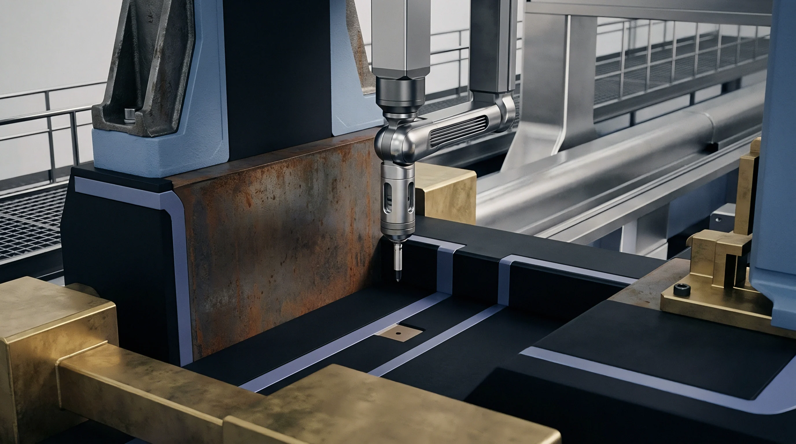

Sensor
Hardware selection determines data quality in ultrasonic propagation tracking systems. Piezoceramic transducers fabricated from lead zirconate titanate or high temperature bismuth titanate mount behind mold cavity walls, core inserts, or ejector pins. Sensors must withstand cyclic clamping forces up to several thousand kilonewtons, mold surface temperatures exceeding 180 degrees Celsius, and peak cavity pressures reaching 2000 bar.
Non-intrusive sensor mounting behind 2 to 5 millimeter steel cavity faces preserves part aesthetics while maintaining mechanical strength across high volume production runs.
Data acquisition cards digitize returning acoustic signals at sampling rates between 50 and 100 megahertz. Microsecond-level signal timing accuracy resolves sound velocity changes down to 0.1 percent, detecting minute shifts in resin density and part weight. Signal cables routed through internal mold wiring channels require heavy shielding against press motor drives and high voltage static discharge from part ejection devices.

Transducer Integration in Multi Cavity Tool Steel
High frequency piezoceramic elements installed behind ejector pins convert mechanical stress pulses into high resolution electrical voltage signals. Direct contact between transducer faces and ejector pin backends minimizes signal loss. Ejector pins function as acoustic wave guides, conducting longitudinal pulses directly from the mold cavity interface to external sensor housings located in cold backing plates.
Machining tolerances on ejector pin fits must remain within 5 micrometers under DIN 16742 guidelines to prevent acoustic energy leaks into surrounding mold plates.
Piezoelectric crystals convert stress to voltage. Mounting sensors behind stationary core pins offers another effective sound transmission path. Stationary pins experience minimal axial displacement, eliminating signal noise associated with sliding friction along ejector pin bores.
Dual transducer setups placing transmitter and receiver on opposing mold cavity halves achieve direct pitch-catch transmission, maximizing acoustic signal-to-noise ratios during high speed cycles.

Acoustic Coupling and Signal Attenuation Controls
Interfacial impedance mismatch between the mold wall steel and molten resin dampens wave amplitude by up to forty decibels. High temperature acoustic coupling agents, such as synthetic silicone greases or thin copper foil discs, eliminate air gaps at dry steel-to-sensor junctions. Eliminating air micro-voids ensures consistent sound amplitude transmission across millions of compression cycles.
Sensor pre-load bolts tightened to exact torque specifications maintain constant mechanical coupling pressure on piezoceramic elements.
- Piezoceramic depolarization occurs when mold temperatures exceed Curie thresholds during extended thermal runaway events.
- Impedance mismatch losses arise from improper acoustic grease application or mechanical gaps at ejector pin interfaces.
- High frequency attenuation severely degrades signal amplitude when processing glass-reinforced or highly filled polymers.
- Signal interference stems from press mechanical vibration or hydraulic valve switching noise corrupting microsecond timing measurements.
Compliance with ISO 294 sensor installation protocols protects transducer elements against localized shear heating and mechanical pin binding.

What Causes Acoustic Velocity Drift across Polymer Cavities?
Tool thermal gradients and localized shear heating alter local acoustic propagation speeds by several meters per second across identical core positions. High cavitation tooling suffers from asymmetrical thermal distribution across manifold blocks and cooling circuits. Outer cavities often run cooler than center cavities, accelerating polymer skin formation and altering longitudinal sound transit times.
Cold runner splits introduce fill shear. Variations in shear heating alter melt temperature entering each cavity, creating measurable acoustic speed differences across the tool layout.
Standard purchasing terms under DIN 16742 Grade TG3 mandate automated cavity sorting interfaces whenever real-time acoustic velocity deviations exceed contract limits.


Imbalance
Filling variations across 64 and 128 cavity tools introduce part weight scatter, dimensional instability, and high scrap rates. Traditional cavity pressure transducers track peak pressure but fail to capture local flow velocity variations during early mold cavity filling. Acoustic propagation tracking monitors the exact arrival instant of the polymer melt front across every cavity location.
When melt touches the sensor interface, acoustic transmission begins instantly, establishing zero-time markers for fill balance verification across complex runner systems.
Short shots eliminate acoustic transmission. Cavities receiving insufficient polymer volume show delayed wave arrival times or complete absence of transmitted signal. Press automation software uses acoustic arrival time data to isolate starved cavities, activating targeted hot runner nozzle heaters or adjusting valve gate open sequences to balance melt distribution across the mold face.

Real Time Fill Imbalance Detection in High Cavitation Tools
Volumetric filling variations between individual cavities manifest as distinct arrival time offsets of the longitudinal wave front. In a balanced 32 cavity tool, acoustic arrival times across all cavity sensors align within a tight 5 millisecond window. Thermal expansion shifts core geometry.
Manifold thermal imbalance or runner wall wear expands this window to 50 milliseconds or more, signaling flow hesitation and short shot risks in lagging cavities.
| Cavity Position Zone | Mean Melt Arrival (ms) | Acoustic Velocity (m/s) | Part Weight (g) | Weight Variance (%) |
|---|---|---|---|---|
| Center Zone (Cavities 1-8) | 142.5 | 1410 | 2.45 | +0.41 |
| Mid Radius (Cavities 9-24) | 144.2 | 1402 | 2.44 | 0.00 |
| Outer Boundary (Cavities 25-32) | 148.8 | 1385 | 2.41 | -1.23 |
Acoustic velocity tracking identifies regional density deficits prior to part ejection. Cavities exhibiting reduced sound speed during packing yield lighter parts with lower structural strength. Real-time feedback loops adjust hold pressure profiles dynamically, maintaining uniform part density despite batch resin viscosity variations.

Gate Freeze off Monitoring and Decoupled Control
The transition from liquid shear flow to solid state packing at the cavity gate creates a sharp inflection in signal propagation speed. Gate freeze shifts arrival timing. Once the gate freezes completely, cavity pressure drops while acoustic velocity reaches a stable plateau corresponding to solid polymer cooling rates.
Monitoring acoustic velocity inflection points establishes the precise minimum required holding time for each production mold.
- Cavity fill triggering enables automated decoupling from injection to packing phase based on acoustic front arrival.
- Gate seal identification pinpoints the exact millisecond flow ceases, optimizing holding time settings.
- Viscosity shift compensation automatically adjusts barrel temperature profiles when resin lot variations occur.
- Part ejection validation confirms complete part release before mold closure, preventing tool crashes.
Cycle times drop under automated sorting. Cutting unnecessary holding time seconds shortens overall production cycles without compromising part dimensional tolerances. Tracking gate freeze across all cavities prevents premature pack signal shut-off, eliminating sink marks and void formations across thick-walled component features.
Unchecked filling variations across high cavitation moulds result in undetected short shots, localized flash, and catastrophic tool damage when un-filled cavities alter core pin bending forces.


Settlement
Capital investment in acoustic velocity tracking hardware requires rigorous financial justification based on tooling amortisation and operational scrap reduction. Equipping a 64 cavity tool with ultrasonic sensors increases initial tooling expenses by 15 to 22 percent compared to baseline cavity pressure installations. Savings stem from automated scrap segregation, zero-defect production guarantees, shortened cycle times, and extended mold life achieved through balanced cavity loading profiles.
Tooling buyers evaluate landed piece costs against total quality risk. In medical component manufacturing, where defective parts trigger complete batch quarantine, real-time acoustic verification pays for hardware installation costs within months of commercial press startup.

Capital Expenditure and Scrap Rate Economics
A 64 cavity tool producing polypropylene medical syringe barrels generates millions of cycles annually across high speed production runs. Operating at four second cycle times, a one percent scrap rate generates over five hundred thousand defective parts per year, consuming raw material and wasting machine press capacity. Acoustic velocity monitoring identifies out-of-spec cavities on the current shot, driving robotic drop chutes to segregate suspect parts instantly without stopping the machine press.
Preventive maintenance scheduling improves when acoustic data reveals progressive core wear or cooling line fouling. Early detection of thermal channel scaling prevents heat buildup, protecting multi-cavity tool steel against localized structural cracking and flash generation.

Worked Cost Model for Automated Cavity Quality Sorting
Consider a 128 cavity mould operating at a six second cycle time producing low density polyethylene closure caps. Machine operating expenses average 65 dollars per hour, while polymer resin costs 1.85 dollars per kilogram. Scrap rates under standard press control hover at 1.8 percent due to thermal drift across night shifts.
| Control Metric Strategy | Initial Tooling Add-On ($) | Annual Scrap Rate (%) | Annual Material Loss ($) | Payback Period (Months) |
|---|---|---|---|---|
| Standard Hydraulic Pressure | 0 | 2.40 | 42,600 | N/A |
| Cavity Pressure Sensors (8 Position) | 28,000 | 1.10 | 19,500 | 14.5 |
| Full Acoustic Velocity Tracking (128 Cavity) | 62,000 | 0.15 | 2,660 | 18.6 |
Installing complete ultrasonic velocity tracking reduces scrap rates to 0.15 percent. Savings in raw material resin exceed 39,000 dollars annually, while machine time savings recover an additional 18,000 dollars in productive capacity. Total annual financial payback recovers sensor integration investment within nineteen months of continuous operation.
Monitoring acoustic velocity shifts across multi-cavity tooling eliminates scrap before dimensional defects manifest on finished parts.
Whether sensor durability across tens of millions of high pressure cycles justifies eliminating offline dimensional sampling remains an open question for tooling engineers managing high volume production lines.