Uniaxial Tensile Test Limitations in Amorphous Polymer Engineering
Uniaxial tensile test data fails to predict brittle fracture in amorphous polymers where internal radii, weld lines, and packing stresses induce multiaxial loads.
Yield
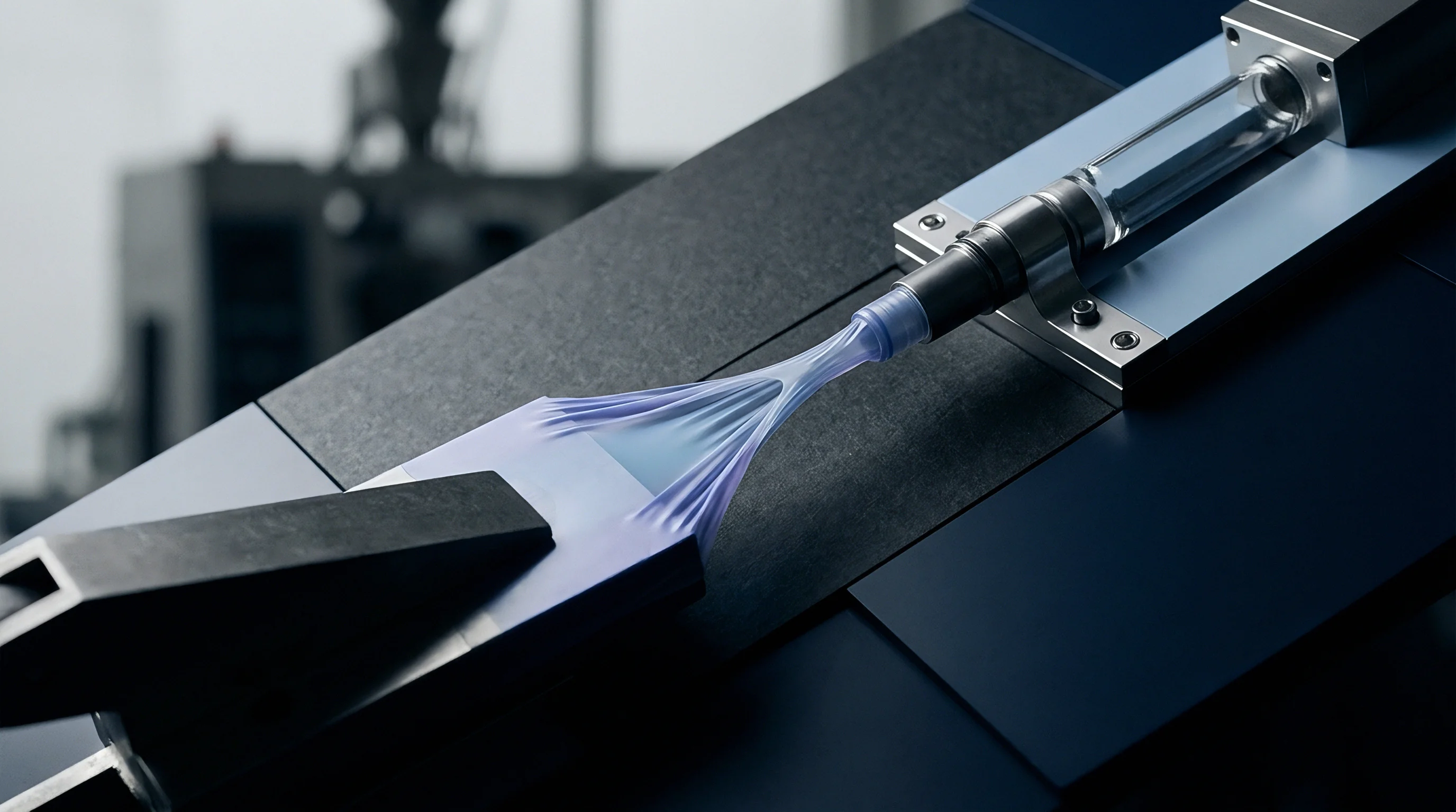
Tensile bars pull under pure axial tension. Standard test specimens moulded under ISO 527-2 Type 1A or ASTM D638 Type I measure linear displacement at twenty-three degrees Celsius and fifty percent relative humidity. That raw number populates the resin datasheet.
The production press operates under different physics. Molten resin injects into cold tool steel under pressures often exceeding one thousand bar, creating orientation gradients from surface to center. Amorphous thermoplastics, including polycarbonate, polymethyl methacrylate, polyetherimide, and polysulfone, exhibit mechanical yield behavior governed by hydrostatic pressure.
Hydrostatic stress remains zero in pure torsion and negative in uniaxial tension, but turns positive under triaxial constraints. Uniaxial tension tests conceal this sensitivity.

Tensile Bar Geometry and Pressure Sensitivity
Standard injection moulds produce test coupons with uniform cross sections free from external stress concentrations. The ISO dogbone geometry suppresses triaxial stress development, allowing polymer chains to rotate and align along the pulling axis. In actual production mouldings, parts carry ribs, bosses, snap-fits, and varying wall thicknesses.
These features induce complex multiaxial stress states. Amorphous resins follow pressure-dependent yield criteria, described by the modified von Mises or Drucker-Prager models. The yield stress increases linearly with hydrostatic pressure.
Tensile test data measures yield at a single hydrostatic pressure value, rendering the metric unreliable for complex geometries where triaxial stresses prevent yielding.
Tensile modulus calculations assume isotropic material behavior. Injection-moulded amorphous polymers develop frozen-in molecular orientation along the flow path, creating mechanical anisotropy. The skin layer experiences intense shear during cavity filling, freezing stretched polymer chains against the chilled cavity wall.
The core experiences slower cooling, permitting molecular relaxation. Testing a machined coupon cut parallel to the flow path yields a higher tensile modulus and tensile strength than a coupon cut perpendicular to flow. A single datasheet value ignores this internal morphology entirely.
Hydrostatic tension suppresses plastic yielding and promotes brittle cavitation inside thick amorphous sections.

Shear Bands versus Dilatational Crazing
Amorphous chain entanglements dissipate strain energy through two distinct molecular modes. Shear yielding involves localized shear banding without volume change, maintaining optical transparency and ductile energy absorption. Crazing involves microvoid formation, cavitation, and fibril breakdown, resulting in volumetric expansion and brittle rupture.
Uniaxial tensile tests on ductile amorphous resins like polycarbonate typically trigger shear yielding, presenting an impressive nominal elongation at break above eighty percent. A triaxial stress state inside a moulded component suppresses shear stresses while maximizing volumetric expansion. The material undergoes catastrophic crazing at strain levels below three percent.
| Polymer Chemistry | Datasheet Tensile Yield (MPa) | Datasheet Elongation at Break (%) | Compressive Yield Stress (MPa) | Critical Crazing Strain (%) | Dominant Failure Mode in Triaxial Stress |
|---|---|---|---|---|---|
| Polycarbonate (General Purpose) | 62 to 68 | 90 to 120 | 75 to 82 | 0.75 to 0.90 | Brittle Crazing |
| Polymethyl Methacrylate (PMMA) | 68 to 74 | 3 to 6 | 95 to 105 | 0.35 to 0.50 | Brittle Fracture |
| Polyetherimide (PEI) | 100 to 110 | 50 to 70 | 140 to 155 | 0.80 to 1.05 | Microvoid Cavitation |
| Polysulfone (PSU) | 70 to 78 | 40 to 80 | 90 to 100 | 0.65 to 0.85 | Brittle Crazing |
| Acrylonitrile Butadiene Styrene | 42 to 50 | 20 to 40 | 55 to 65 | 0.50 to 0.70 | Stress Whitening and Rupture |
Compressive yield strength exceeds tensile yield strength by twenty to forty percent across all amorphous grades. The pressure coefficient determines how rapidly yield strength climbs when compressive or hydrostatic forces rise. Designers evaluating an enclosure or pressure vessel using solely the tensile yield value overestimate the plastic deformation capacity of the material under internal pressure.
The toolroom cuts steel based on nominal stress predictions, only to discover parts cracking during burst testing at half the calculated load. The true mechanical boundary remains unresolved when test standards isolate a single axis.


Notch
Sharp internal radii act as mechanical amplifiers. A radius transition inside an injection-moulded chassis concentrates load lines, creating localized multiaxial tension. Standard tensile dogbones feature sweeping transition radii of sixty millimeters or more, deliberately eliminating stress concentrations to measure bulk response.
Real functional mouldings cannot accommodate such generous transitions without violating space envelopes, compromising shut-offs, or producing sink marks on cosmetic surfaces.
How Do Multiaxial Stress Fields Suppress Shear Yielding?
Plane strain conditions dominate thick wall intersections. When a tensile load acts on an unnotched bar, Poisson contraction narrows the width and thickness directions, facilitating octahedral shear strain. When an internal notch or sharp corner enters the geometry, the surrounding rigid material prevents lateral contraction.
The transverse stresses climb, matching the primary axial stress and generating a triaxial tensile field. Octahedral shear stress drops toward zero. Plastic shear yielding stops completely.
The polymer behaves in a brittle manner, initiating rapid crack propagation along crazing planes.
A fillet radius below 0.6 times the wall thickness drops the impact energy of unfilled polycarbonate from 750 Joules per meter to under 120 Joules per meter at room temperature.
Triaxiality at Internal Radii
Fillets smaller than half the nominal wall thickness generate severe hydrostatic tension. Injection-moulded amorphous polymers lack the grain boundary slip mechanisms present in metals, relying on entangled macromolecular coils to uncoil under shear. The presence of triaxial tension pulls these coils apart dilatatively, tearing entangled chains at loads far below the datasheet tensile yield value.
Engineering drawings regularly permit internal corner radii as tight as 0.2 millimeters to achieve sharp aesthetic styling. The resulting parts fracture during assembly operations, while the material supplier produces a certificate of analysis proving nominal tensile strength complies with ASTM specifications.
Wall thickness transitions exacerbate this vulnerability. Core pins, shut-offs, and lifter edges introduce localized geometry changes that distort stress distributions. Toolmakers cut these details directly into hardened tool steels like H13 or P20.
Modifying an internal radius after tool build involves electrical discharge machining, electrode fabrication, and re-polishing, costing thousands of dollars per cavity. Designing parts purely from uniaxial tensile parameters guarantees tooling revisions once physical testing exposes the plane strain embrittlement.
Specific moulded features systematically trigger localized multiaxial embrittlement:
- Abrupt wall transitions prevent uniform cooling and concentrate multi-directional tensile forces directly at the step change.
- Blind core pins generate severe hoop stresses combined with longitudinal pull forces during part ejection.
- Rib-to-wall intersections create localized thermal mass, inducing volumetric voiding and tensile stress concentrations under structural loads.
- Gated edge margins combine high frozen orientation with notch sensitivity, creating immediate crack initiation sites under bending deflections.
When buyers rely on unnotched tensile strength metrics, field warranty exposure increases directly with part geometric complexity.
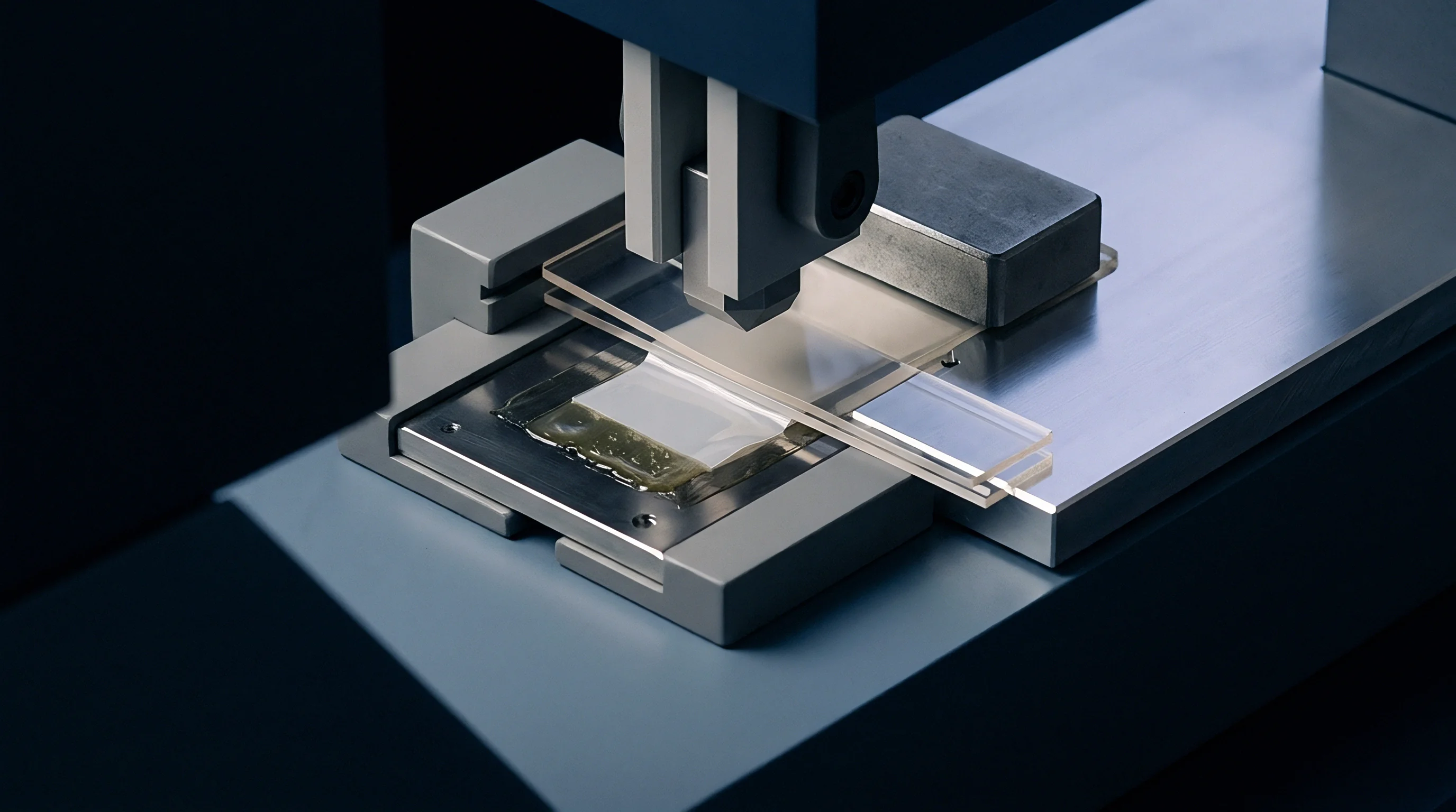
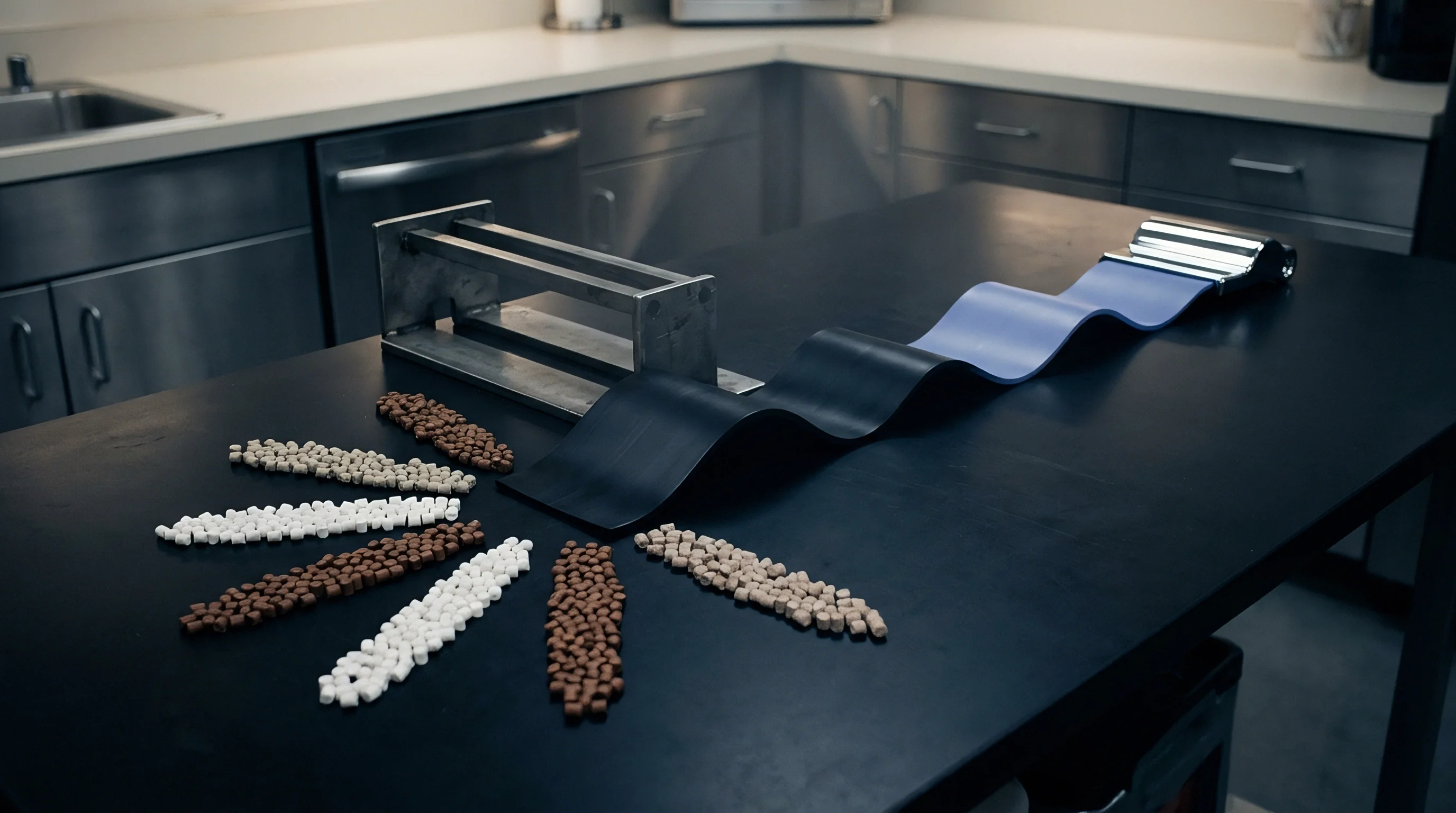
Drift
Amorphous polymers exist in a non-equilibrium thermodynamic state below glass transition. The rapid cooling cycle of an injection press freezes polymer chains before they achieve thermodynamic equilibrium. Free volume remains trapped between macromolecular segments.
Over weeks, months, and operational thermal cycles, amorphous materials undergo physical aging. Chains relax toward a denser molecular arrangement, shedding free volume and shifting yield points. Tensile properties recorded twenty-four hours after moulding misrepresent the stiffness and ductility of the part in service.

Can Standard Tensile Modulus Predict Creep Rupture?
Datasheet stiffness reflects a five-minute test window. Standard ISO 527 tests pull specimens at crosshead speeds between one and fifty millimeters per minute, capturing instantaneous response. Functional parts in service carry continuous static loads, such as threaded fastener preloads, fluid pressures, or spring engagement forces.
Under sustained load, amorphous plastics exhibit viscoelastic creep. Viscoelastic strain accumulates logarithmically over thousands of hours, steadily decreasing effective structural stiffness.
Creep modulus values fall to a fraction of the instantaneous tensile modulus. For general-purpose polycarbonate loaded at twenty megapascals, the apparent modulus drops from twenty-four hundred megapascals at one minute to thirteen hundred megapascals at three thousand hours. When engineers size structural wall sections using raw datasheet tensile modulus, parts slowly deform, loosen threaded joints, and bind adjacent mechanisms.
At elevated operational temperatures, this compliance acceleration shortens component lifespan.
| Polymer Grade | Instantaneous Modulus (MPa) | 100-Hour Modulus at 23°C (MPa) | 1,000-Hour Modulus at 23°C (MPa) | 1,000-Hour Modulus at 60°C (MPa) | Apparent Modulus Loss at 1,000h 60°C (%) |
|---|---|---|---|---|---|
| Polycarbonate (Unfilled) | 2,350 | 1,720 | 1,450 | 980 | 58.3 |
| PMMA (Moulding Grade) | 3,100 | 2,150 | 1,800 | 1,100 | 64.5 |
| Polysulfone (PSU) | 2,500 | 2,100 | 1,950 | 1,620 | 35.2 |
| Polyetherimide (PEI) | 3,300 | 2,850 | 2,650 | 2,300 | 30.3 |
| ABS (High Heat Grade) | 2,200 | 1,400 | 1,150 | 620 | 71.8 |
Creep rupture limits represent a distinct physical threshold. Under static loading, an amorphous material fractures at stresses far below its nominal tensile strength. A polycarbonate component loaded continuously at forty megapascals cracks in air within two hundred hours, despite exhibiting a tensile yield strength of sixty-five megapascals on the resin supplier datasheet.
The failure occurs via slow crack growth driven by local chain disentanglement. The short-duration tensile pull provides zero information regarding the creep rupture envelope.
Sustained mechanical loads over time cause brittle failure at stresses well below the instantaneous tensile yield point.

Physical Aging and Environmental Cracking
Molecules slowly consolidate free volume during post-moulding storage. This density increase elevates the tensile modulus and yield point while sharply eroding ultimate elongation and impact toughness. A polycarbonate housing exhibiting ductile yielding on the press floor becomes brittle after ninety days of shelf life at ambient temperature.
Free volume loss restricts molecular motion, lowering the energy barrier required for crazing initiation.
Environmental stress cracking amplifies this degradation pathway. In the presence of chemical agents such as cleaning solvents, industrial lubricants, or plasticizers from adjacent flexible vinyl seals, amorphous networks swell locally. The active fluid penetrates microvoids, plasticizing chain entanglements and slashing the critical crazing stress.
A component carrying tensile residual stresses as low as ten megapascals shatters within minutes of chemical contact. Standard uniaxial tensile tests conducted in inert air provide zero warning of chemical compatibility boundaries.
Viscoelastic strain prediction demands multi-point isochronous stress-strain curves rather than single-point tensile values.
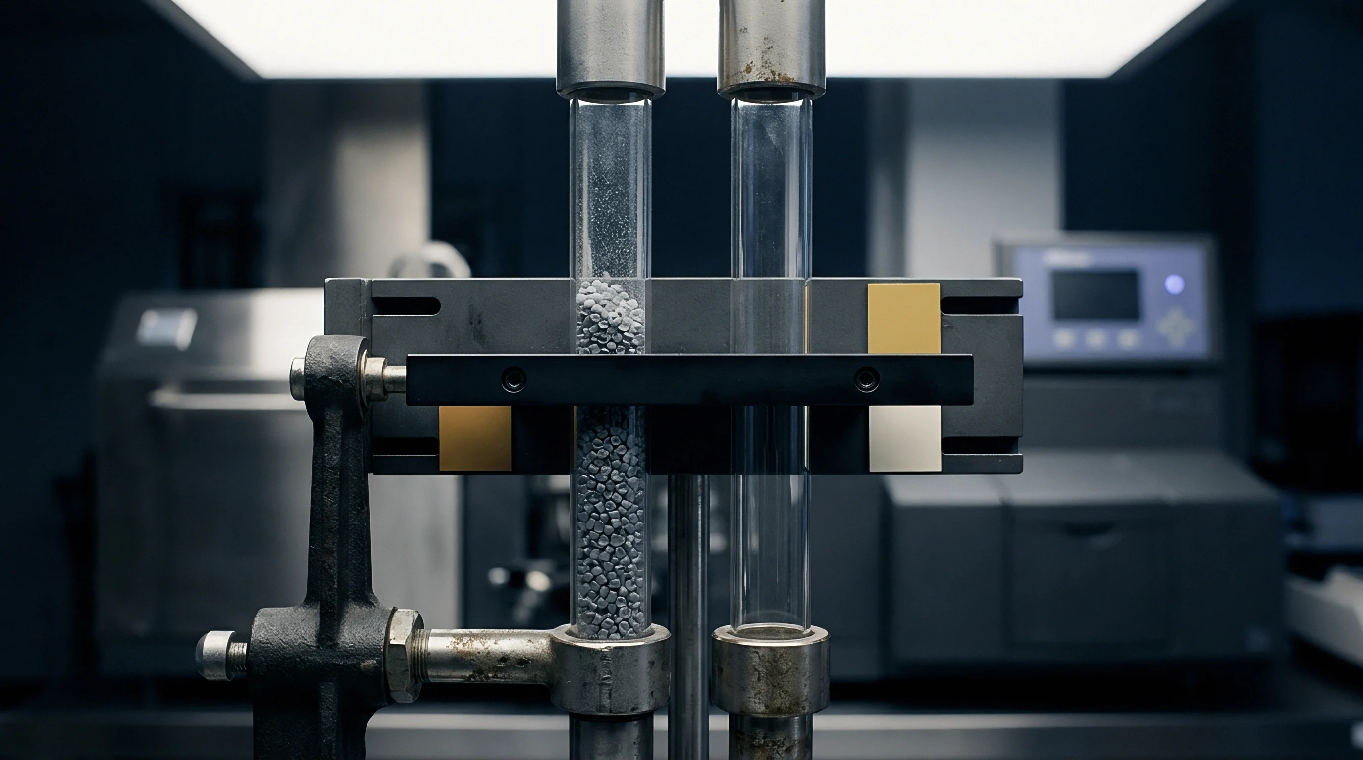
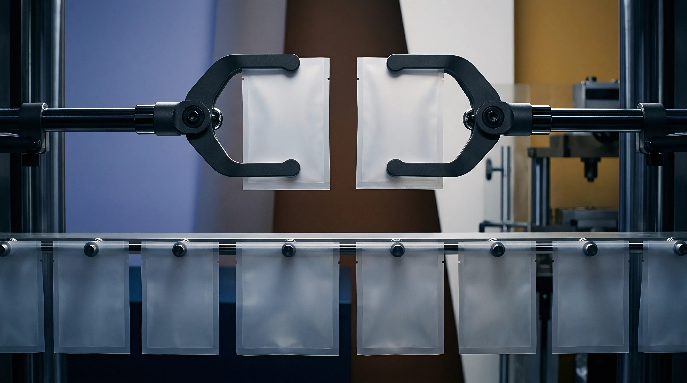
Gate
Melt velocity profiles determine frozen layer thickness. In an injection moulding tool, the polymer melt enters through a sprue, traverses the runner system, squeezes through a restricted gate, and fills the cavity. The fountain flow phenomenon turns chains outward at the advancing flow front, depositing them against chilled steel walls.
This mechanism builds distinct morphological layers through the part thickness. Standard tensile bars moulded in end-gated single-cavity prototype tools exhibit highly aligned skin layers along the pulling axis. Production tools feature multiple gates, complex flow splits, and cooling circuits running around ejector pins.

Flow Orientation and Weld Line Weakness
Polymer chains align parallel to the fill direction during cavity injection. Transverse to the flow direction, chains exhibit minimal entanglement, creating an internal plane of weakness. If a production part requires gating that forces melt across the primary loading axis, its actual tensile load capacity drops twenty to thirty-five percent below the supplier datasheet.
Even worse performance appears at weld lines.
When two melt fronts meet after flowing around an aperture or core pin, fountain flow prevents interdiffusion of molecular chains across the interface. The polymer chains freeze oriented parallel to the weld seam. Tensile strength perpendicular to a cold weld line in an amorphous resin like ABS or PMMA drops by forty to seventy percent relative to the bulk material.
Standard tensile coupons tested under ISO 527 contain no weld lines. The tool designer relying on datasheet figures places gates in locations that drive weld lines into critical structural zones, guaranteeing field fractures.
Optimizing injection press parameters helps suppress extreme residual stresses through a systematic sequence:
- Melt temperature profiling balances shear heating against thermal degradation across the screw recovery stroke.
- Fill speed velocity stepping maintains a constant linear melt front speed, preventing premature skin formation.
- Cavity pressure sensing verifies that pack-and-hold pressure transfers effectively past the gate before gate freeze-off occurs.
- Cooling channel flow verification ensures turbulent flow with Reynolds numbers above four thousand to prevent uneven core-to-cavity shrinkage.

Thermal Quenching across Thick Sections
Differential cooling between part surface and core induces severe residual stresses. The exterior skin freezes instantly against the chilled mould steel, setting the overall envelope dimension. The molten core cools much more slowly, contracting against the already rigid shell.
This thermal contraction places the core in hydrostatic tension while putting the surface into compression. In thick sections exceeding three millimeters, core hydrostatic tension initiates internal microvoiding without any external applied load.
When external loads act on a moulding carrying severe internal residual stress, the local internal stress sums directly with the applied load. A part carrying thirty megapascals of frozen-in tensile stress fails under an applied tensile load of only thirty-five megapascals, despite a resin specification sheet claiming a sixty-five megapascal yield limit. Suppliers often claim that moulding defects and premature cracking stem from improper customer processing rather than material limits.
Quote
Tool drawings specify geometry without defining internal stress states. When procurement teams issue requests for quotation, they attach 2D drawings and CAD models, referencing generic resin trade names and basic ASTM or ISO data sheets. Toolmakers price the mould based on cavity count, steel grade, slide mechanisms, and cycle time assumptions.
Testing coupons cannot substitute for functional component validation under real assembly constraints. Tooling money committed before multiaxial stress evaluation risks expensive re-tooling.

Biaxial Qualification Costs against Cavitation Scale
Financial commitments escalate rapidly when tools enter machining. Cutting a 16-cavity production tool for an amorphous medical device component commits three hundred thousand dollars in capital before first shot delivery. If structural weakness appears during device assembly due to triaxial constraint cracking at a snap-fit, re-engineering the tool requires steel alterations, lifter modifications, and cycle-time penalties.
Conducting biaxial disc puncture tests under ASTM D3763 or high-speed multiaxial impact tests on prototype parts costs less than five thousand dollars. Skipping this validation leaves the tooling investment exposed.
| Test Protocol | Standard Designation | Data Produced | Cost per Test Series (USD) | Design Defect Detection Rate |
|---|---|---|---|---|
| Uniaxial Tensile Test | ISO 527 / ASTM D638 | Single-axis modulus, yield stress, nominal elongation | 350 to 600 | Under 15% of assembly failure modes |
| Biaxial Disc Puncture | ASTM D3763 / ISO 6603 | Multiaxial yield, puncture energy, ductile-brittle transition | 1,200 to 2,000 | Detects 65% of impact and plane strain defects |
| Creep Rupture Matrix | ASTM D2990 / ISO 899-1 | Isochronous modulus curves, long-term rupture thresholds | 4,500 to 9,000 | Detects 90% of sustained load and relaxation failures |
| Birefringence Stress Audit | ASTM D4093 | Frozen-in residual stress map across moulded part | 800 to 1,500 | Identifies 80% of gate-induced crack initiation sites |
| Finished Part Proof Burst | Internal Factory Protocol | True collapse pressure, weld line retention factor | 2,500 to 5,000 | Detects 95% of geometry and tooling defects |
Tool amortisation schedules depend entirely on predictable cycle times. To minimize cycle time, press operators frequently run mould temperatures lower than recommended, chilling the tool to thirty degrees Celsius instead of eighty degrees. This choice freezes excessive orientation into the part, destroying impact performance while cutting three seconds off cooling time.
A buyer reviewing piece prices must evaluate the total landed cost, factoring in post-assembly scrap rates caused by brittle cracking.
A contract clause mandating post-moulding birefringence audits per ASTM D4093 shifts dimensional and residual stress responsibility back to the moulder before tool sign-off.
Procurement documents should stipulate that resin compliance certificates reference isochronous creep data and environmental stress cracking limits rather than bare tensile yield values. Purchase agreements incorporating DIN 16742 tolerance grades and residual stress caps compel suppliers to validate cooling uniformity across all cavities. Tools signed off without multiaxial verification transfer financial liability for field failures directly to the buyer.