Transient Thermal Shock Drift and Signal Hysteresis Compensation in Multi-Cavity Micro-Moulding Instrumentation
Dynamic sensor thermal compensation and pin hysteresis reduction secure tight process windows and low scrap rates in multi-cavity micro-moulding tools.
Shock
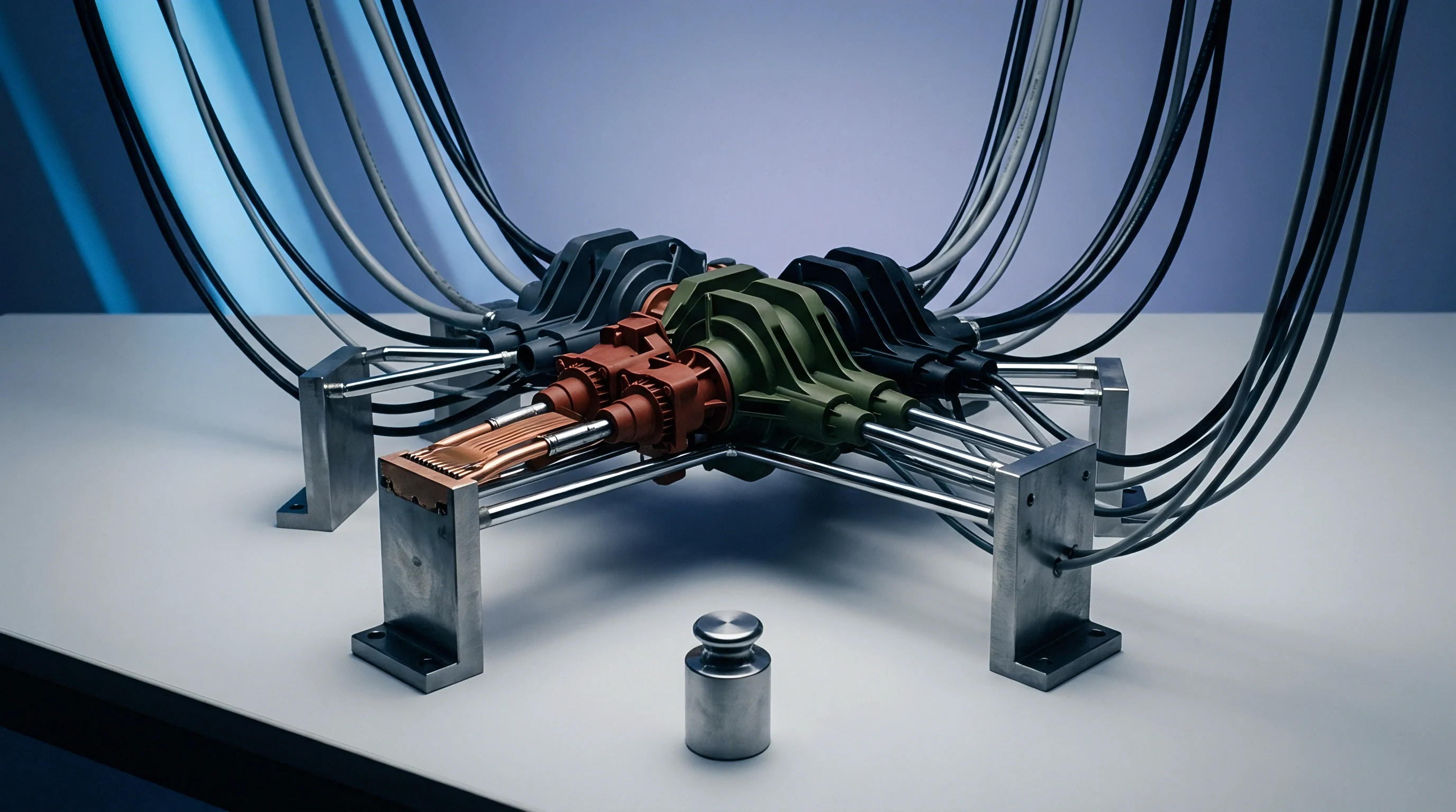
Molten polymer entering a micro-cavity at 320°C produces a thermal flux gradient exceeding 200°C per millisecond across the exposed diaphragm of an in-cavity pressure transducer. In micro-moulding applications where fill times run below 0.03 seconds and total shot mass stays under 0.5 grams, this instant rise in surface temperature alters sensor mechanics before cavity pressure reaches its peak. Piezoelectric quartz elements exhibit pyroelectric charge separation under sudden thermal expansion, generating an artificial voltage spike that registers as pressure before mechanical force touches the sensor face.
Piezoresistive dynamic elements experience rapid resistance shifts across their Wheatstone bridge arms due to non-uniform heat transfer through the sensor housing. The resulting voltage output combines physical cavity pressure with transient thermal drift, obscuring the true melt front arrival and skewing automated switchover signals.
Micro-injection processes rely on cavity pressure thresholds to trigger the transition from high-velocity injection to packing pressure. A sensor corrupted by thermal shock signals premature cavity fill, forcing the machine controller to drop injection velocity before the melt reaches thin-wall cavity boundaries. Unfilled micro-features, flash along parting lines, and structural voids follow directly from this timing error.
Quartz crystals generate charge. When heat diffuses through the front membrane into the crystal assembly over the subsequent 200 milliseconds, the initial pyroelectric charge dissipates, leaving a depressed pressure trace that reads lower than actual melt force during the critical packing phase.
Thermal transient spikes on uncompensated micro-cavity pressure sensors alter V/P switchover timing by up to 14 milliseconds during fill phases under 0.03 seconds.
The magnitude of transient drift scales inverse to sensor diaphragm mass. Standard industrial transducers incorporate protective thermal barriers that damp temperature gradients, but micro-moulding geometry restricts sensor tip diameters to 1.0 mm or less. Reduced membrane thickness lowers mechanical inertia while accelerating thermal conduction into sensitive internal elements.
Direct-contact sensors mounted flush with the cavity wall suffer maximum shock, while indirect transducers seated behind ejector pins experience a delayed, attenuated thermal curve accompanied by mechanical friction delays.
| Sensor Construction | Diaphragm Diameter (mm) | Thermal Shock Drift (bar equivalent) | Rise Time (ms) | Pyroelectric Sensitivity |
|---|---|---|---|---|
| Flush Piezoelectric Quartz | 1.0 | 35 to 85 | 0.005 | High |
| Indirect Piezoelectric (Pin Load) | 0.5 (Pin) | 10 to 25 | 0.045 | Moderate |
| Flush Piezoresistive Strain-Gauge | 1.5 | 45 to 110 | 0.012 | None (Thermal Offset) |
| Thin-Film Piezoresistive Micro-Tip | 0.8 | 20 to 50 | 0.008 | None (Bridge Unbalance) |
Multi-cavity tools multiply thermal drift variance across cavities. Flow length discrepancies, hot runner nozzle temperature variations, and cooling channel distance offsets produce unique thermal shock profiles for each individual cavity. Applying a single global pressure threshold across a 32-cavity tool forces the press controller to average corrupted signals.
Cavities nearest the sprue experience earlier thermal shock spikes, while distal cavities lag, producing inconsistent part weights and dimensional spread exceeding engineering limits.
Improper setting of switchover points driven by uncompensated sensor drift leads to localized short shots, variable flash generation, and dimensional non-conformance across multi-cavity micro-moulding batches.
Friction
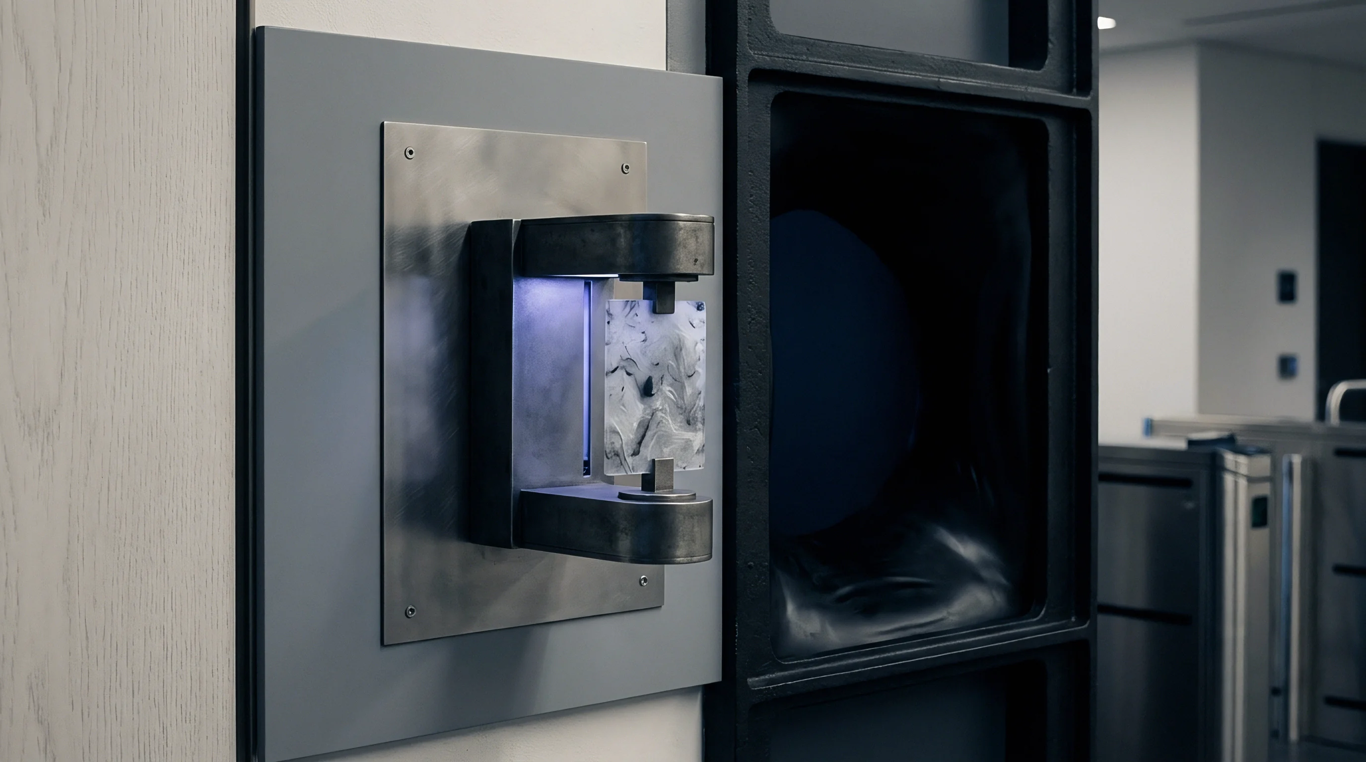
Pin movement within precision-bored tool steel channels creates non-linear mechanical hysteresis during force transfer to indirect pressure sensors. Micro-moulding tooling uses indirect force transmission pins down to 0.5 mm in diameter to transfer cavity melt pressure to sensors recessed inside the mold plate. As molten liquid polymer fills the cavity under pressures up to 1800 bar, high side-loads push the pin against its guide bore.
Frictional forces oppose pin movement during the rising pressure phase, requiring higher melt pressure to move the pin than the sensor records. Mechanical clearance allows tiny polymer chains to enter the annular gap around the pin, forming a thin polymer film that increases sliding resistance.
During the cooling cycle, cavity pressure drops while the polymer freezes. Frictional drag along the pin sidewall prevents the pin from returning smoothly to its rest position. The sensor continues registering residual compression after cavity pressure has dropped to zero.
This mechanical hysteresis loop splits the loading path from the unloading path, creating a signal deviation between fill-pack phases and cooling-ejection phases. Signal hysteresis skews switchover.
Sensor structural geometry contributes additional mechanical hysteresis through internal membrane deflection. Diaphragms undergo elasto-plastic stress distribution when loaded near maximum rating. Repeated micro-moulding cycles at 100 Hz shock frequencies induce micro-yield phenomena within the sensor membrane, shifting the baseline zero point between consecutive shots.
- Pin clearance binding occurs when side-loads force the transmission pin against the guide sleeve, generating asymmetric friction that reduces measured pressure during cavity loading.
- Polymer film bridging develops as low-viscosity resin migrates into the 2-micron radial pin clearance, creating viscous shear resistance that holds residual force on the sensor head during unloading.
- Diaphragm edge constraint arises from high installation torque applied to sensor lock nuts, causing circumferential stress gradients that distort baseline membrane return paths.
- Thermal expansion mismatch between tool steel cavities and stainless steel transducer bodies creates differential radial clamping forces as mold temperatures fluctuate across production shifts.
Quantifying the split between mechanical pin drag and internal membrane hysteresis requires baseline calibration without resin flow. Tool steel holds layout. Press-side setters observe loading-unloading pressure curves during dummy mechanical dry cycles to separate mechanical binding from melt dynamics.
Friction distorts signal release. When mechanical pin hysteresis exceeds 5% of maximum reading, residual pressure signals prevent press controllers from detecting actual gate freeze-off timing, leaving cycle time optimisation to rough guesswork.
What structural margin exists between pin clearance tolerances that prevent melt ingress and those that minimize mechanical side-load friction across 500,000 continuous cycles?

Channel
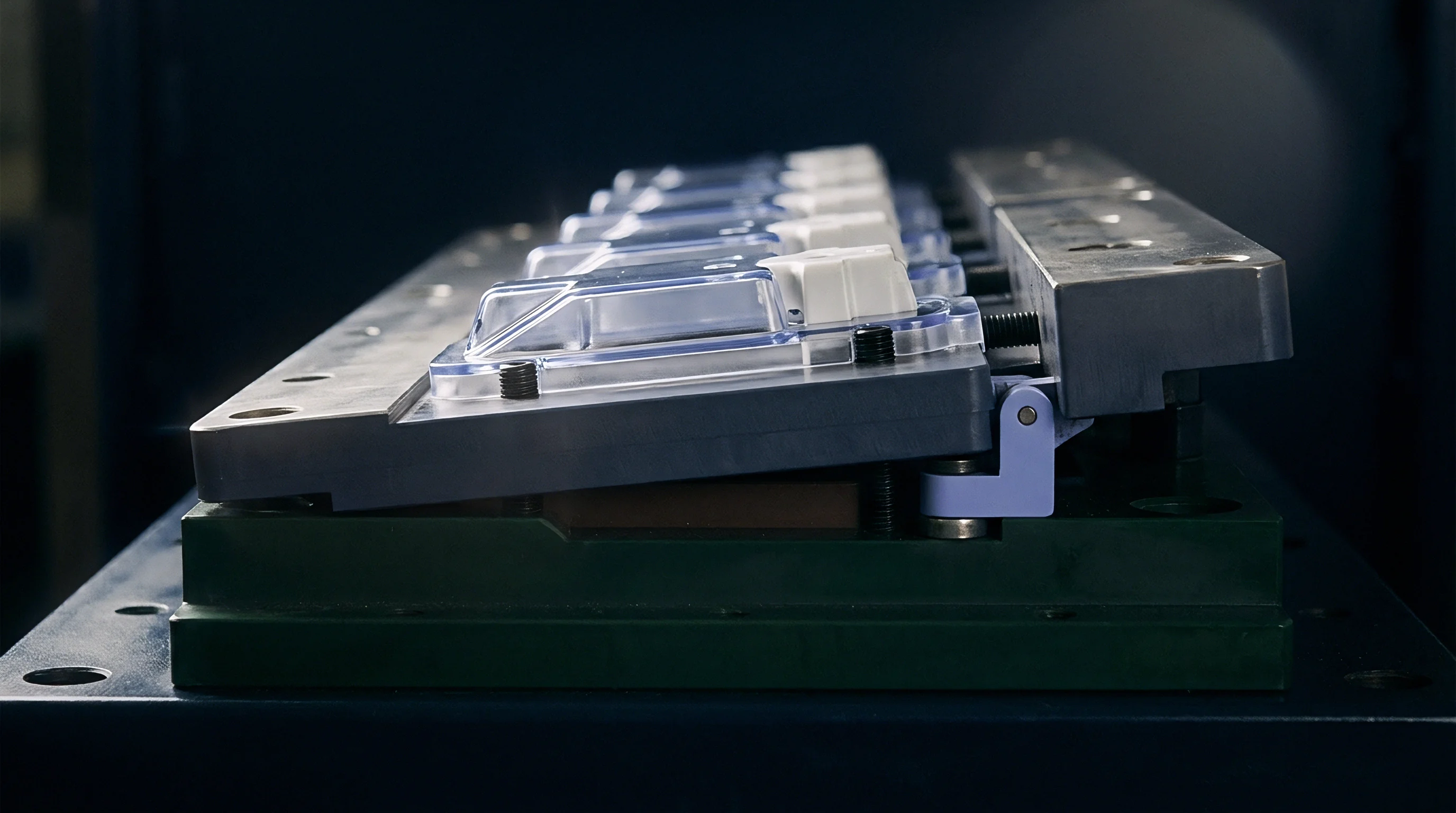
Machining sensor pockets directly into multi-cavity plates requires strict thermal isolation and precise physical support geometry. Indirect transducer channels need clean force-transmission pathways isolated from hot runner radiant heat and cooling line thermal sinks. Steel plates heat up under production load.
Placing a pressure transducer within 8 mm of a hot runner drop elevates the sensor body temperature beyond its compensated operating window, causing continuous thermal zero drift. Ceramic insulating sleeves placed around sensor housings reduce heat conduction from the mold frame, maintaining transducer electronics within tight thermal boundaries.
Direct-mount sensor pockets present distinct machining challenges. A 1.0 mm sensor tip requires a flat, burr-free seat with surface roughness better than Ra 0.2 microns to establish uniform contact with cavity walls. Tilted seating surfaces introduce bending moments across the sensor diaphragm, causing artificial hysteresis during high-pressure packing phases.
Machining tolerances on pocket depth must hold within 0.005 mm to prevent the sensor tip from protruding into the runner stream or receding to form a polymer flash trap.
In indirect sensor mountings, ceramic isolation sleeves reduce thermal drift rates by keeping transducer housing variations within 0.5°C per minute during continuous production runs.

Which Mounting Geometry Prevents Thermal Shock Signal Decay?
Flush cavity mounting exposes the transducer directly to melt pressure, eliminating pin friction losses. Direct exposure subjects the thin steel membrane to maximum thermal shock forces. Indirect mounting behind a precision ejector pin isolates the sensor membrane from direct melt contact, filtering out severe temperature spikes.
The indirect pathway introduces pin friction, clearance wear, and potential polymer flash ingress into the pin bore.
Choosing between mounting styles depends on micro-part features, wall thickness, and allowable surface marks. Parts demanding pristine cosmetic surfaces or strict micro-fluidic channel geometries cannot tolerate witness marks left by flush sensor heads. Indirect pin mounting remains necessary for such components, requiring physical channel design adjustments to compensate for mechanical energy losses.
- Bore the indirect sensor pocket concentric to the ejector pin guide hole within 0.003 mm total indicator reading.
- Lap the guide pin sliding surface to a mirror finish of Ra 0.05 microns, eliminating machining marks that trap polymer debris.
- Install a hardened ceramic thermal insulator sleeve around the transducer body to isolate it from mold plate heat sinks.
- Set the sensor pre-load adjustment screw using a calibrated torque wrench to achieve the manufacturer-specified baseline force on the quartz element.
- Verify mechanical return freedom by measuring zero-point voltage stability across ten dry tool actuations at operating mold temperature.
Proper channel preparation balances mechanical rigidity against thermal isolation, protecting sensor accuracy across long manufacturing campaigns. Tooling designs that sacrifice transducer pockets for simplified water channel layouts face unpredictable signal drift during press startup. Thermal gradients offset zero.
Precision pocket alignment keeps mechanical signals repeatable shot after shot.
Indirect pin channels require smooth surfaces, precise alignment, and ceramic thermal shielding to yield clean pressure data.

Calibration
Real-time digital signal processing algorithms correct raw transducer output before feeding cavity pressure curves to machine controllers. Dynamic compensation requires high sampling speeds, exceeding 10 kHz per channel, to capture fast micro-injection filling phenomena. Amplifiers reset baseline voltage.
Digital filters evaluate incoming signals in real time, separating thermal shock artifacts from true hydraulic melt pressure based on frequency response characteristics and dual-slope mathematical models.
Dynamic zero-point resetting operates immediately prior to melt arrival. The signal processor scans cavity pressure readings while the mold is closed but before the injection screw advances. The controller establishes this resting value as zero pressure, canceling out steady-state thermal expansion offsets and mounting pre-load shifts that occurred during prior cycles.
When the melt front contacts the sensor tip, high-pass response algorithms isolate the high-frequency pressure wave from the slow heat conduction drift curve that builds across the injection cycle.
| Correction Method | Target Defect | Processing Latency (ms) | Drift Suppression Ratio | Computational Load |
|---|---|---|---|---|
| Dynamic Zero Reset | Static Thermal Offset | 0.10 | 100% (Pre-shot) | Low |
| Dual-Slope Thermal Compensation | Pyroelectric Shock Spike | 0.05 | 85 to 92% | Moderate |
| Preisach Polynomial Hysteresis Fit | Pin Mechanical Friction | 0.25 | 75 to 88% | High |
| Adaptive High-Pass RC Filtering | Slow Heat Diffusion Shift | 0.02 | 60 to 70% | Low |
Hysteresis correction models use mathematical hysteresis functions, such as the Preisach or Bouc-Wen models, embedded within press controller software. These algorithms maintain continuous tracking of loading history during the injection cycle. By evaluating peak pressure reached during packing, the algorithm predicts mechanical pin drag along the unloading curve and adjusts the output signal down to match true melt pressure during cooling.
Uncompensated signals create scrap.
Under ISO 20457 calibration guidelines for micro-moulding instrumentation, real-time pressure acquisition system latency must stay under 0.5 milliseconds to ensure precise V/P switchover control.
Dual-sensor cavity profiling provides an alternative physical method to compensate for thermal shock. Positioning a non-contact infrared thermal sensor adjacent to a pressure transducer allows the press controller to measure surface temperature shock directly. Piezoresistive elements drift fast.
Real-time algorithms cross-reference temperature data against pre-calibrated sensor drift tables, subtracting thermally generated voltage components from measured pressure signals in under 0.05 milliseconds.
Equipment vendors often claim built-in software routines eliminate all sensor drift problems automatically. Experienced setters find these automated routines often fail when melt temperatures drift outside narrow preset windows, forcing manual re-calibration of baseline offset curves.

Cost
Outfitting multi-cavity tools with high-speed sensor instrumentation and dynamic signal processing hardware demands significant upfront tooling capital. A 32-cavity micro-moulding tool fitted with individual flush-mount piezoelectric sensors, low-noise charge amplifiers, and real-time controller integration adds 45,000 to 75,000 EUR to total tooling budget compared to an un-instrumented mold. Sourcing practices justify this investment by calculating scrap reduction, reduced setup time, and automated multi-cavity sorting efficiencies over total production volume.
Uninstrumented micro-moulding processes run higher scrap rates due to undetected cavity filling variations. In micro-connector manufacturing using liquid crystal polymers, an uncompensated tool relying solely on machine hydraulic pressure monitoring can exhibit scrap rates between 3% and 7% due to short shots, flash, or internal voids. Cavity pressure tells the truth.
Implementing compensated multi-cavity sensor arrays drops scrap levels below 0.2%, recovering initial tooling instrumentation expenditures within initial high-volume production runs.
| Cost Component | Standard Uninstrumented Tool | Fully Instrumented Tool with DSP Compensation |
|---|---|---|
| Initial Tool Construction Cost | 120,000 EUR | 185,000 EUR |
| Instrumentation & Hardware Cost | 0 EUR | 65,000 EUR |
| Average Cycle Time | 3.2 seconds | 2.7 seconds |
| Baseline Process Scrap Rate | 4.5% | 0.15% |
| Annual Scrap Cost (10M parts/yr) | 31,500 EUR | 1,050 EUR |
| Break-Even Production Volume | Baseline Reference | 2.1 million units |
Take a 32-cavity micro-connector tool operating at a 2.8-second cycle time producing 10 million units per year. Assume a raw material cost of 0.02 EUR per part and machine operating rates of 60 EUR per hour. Reducing scrap by 4.35% saves 30,450 EUR annually in material alone.
Cycle time optimization made possible by real-time cavity pressure gate freeze-off detection trims 0.5 seconds per cycle, yielding an additional 125 machine running hours annually. Cavity balance drives yield.
- CapEx allocation for sensors includes charge amplifiers, high-speed acquisition cards, mold-mounted junction boxes, and low-noise cables rated for continuous high-temperature service.
- Cavity-to-cavity matching budgets cover labor cost for individual sensor calibration, dynamic hysteresis profiling, and parameter configuration across every mold cavity.
- Maintenance reserve provisions factor replacement transducer units, pin re-lapping services, and ceramic sleeve refurbishment into ongoing piece-part cost calculations.
- Quality verification savings calculate reduced dimensional inspection lab hours resulting from 100% automated cavity pressure sorting and part rejection automation.
Procurement agreements for instrumented micro-moulding tools must include specific drift limit criteria. Sampling rates limit resolution. Polymer seals degrade over time.
Sourcing specifications stipulate maximum allowable sensor thermal drift limits under real processing conditions, transferring validation responsibility to the mold builder prior to final tool handover.
Tooling purchase specifications state that sensor thermal drift must not exceed 1.5% of full scale across operating temperatures from 80°C to 200°C during validation runs.