Three Dimensional Thermal Memory Coupling in Non Symmetric Multi Tier Hot Runner Splitters
Non-symmetric multi-tier splitters introduce 3D thermal memory coupling, requiring active zone isolation and shear balance to hold cavity tolerances.

Mass
Heavy tool steel blocks in stacked distributor configurations exhibit large heat capacities that alter local temperature fields over extended production shifts. Heat accumulates inside steel blocks. In multi-tier hot runner systems, the spatial volume of the steel housing around upper runner channels often differs from the steel mass encapsulating lower channels.
This geometry generates asymmetric thermal dissipation pathways. Heat transfers rapidly from outer manifold surfaces exposed to mold air gaps while inner core areas retain thermal energy. When polymer flows through these multi-level networks, the localized thermal environment dictates melt temperature development along each branch.
The heat capacity of tool steel alloys like 1.2343 or 1.2709 structural steel creates a long thermal time constant. When a hot runner system reaches steady-state electrical power inputs, the internal temperature distribution across non-symmetric distributor tiers remains highly sensitive to local steel volume. Upper tiers embedded in larger steel sections experience lower thermal resistance to surrounding cooling plates than mid-tier channels isolated by thermal air gaps.
Consequently, polymer flowing through separate runner tiers encounters distinct wall temperature profiles despite identical heater band output settings.
Melt Dwell Architecture in Stacked Splitter Plates
Fluid flowing through multi-level distributor networks experiences non-uniform residence periods based on channel length and elevation. In a typical two-tier stack mold splitter, the primary inlet feeds a central drop that splits horizontally across an upper manifold plate before dropping vertically to a secondary distributor plate. Polymer molecules traveling through the upper branch absorb heat from the manifold body while undergoing continuous shear deformation along channel boundaries.
Core melt temperatures remain elevated.
The volumetric channel sizing across tiers governs local flow velocities and residence time spectra. If channel diameters remain uniform while flow divides unequally across upper and lower splits, shear rates diverge. Higher flow velocities in primary channels generate concentrated viscous dissipations, whereas lower flow velocities in extended secondary channels allow conduction to dominate.
This shift in thermal transport mechanics creates a three-dimensional thermal gradient across the flow cross-section, establishing a distinct thermal memory in the fluid before it enters the nozzle drops.
A 12°C thermal delta across upper and lower runner levels shifts volumetric shrinkage by 0.35 percent in 30 percent glass-filled polybutylene terephthalate.

Viscous Heating Vectors across Branch Junctions
High wall shear rates near runner elbows convert mechanical pumping energy directly into thermal energy within boundary layers. Viscous shear generates internal heat. The magnitude of this shear heating depends on local melt viscosity, shear rate, and the physical geometry of the splitter junction.
As melt navigates a 90-degree turn from a vertical inlet bush into a horizontal distributor channel, the velocity profile distorts, shifting maximum shear rates toward the inner radius of the turn.
This localized energy conversion creates thermal streaks within the polymer stream. In non-symmetric splitters where flow directions rotate across multiple geometric planes, these thermal streaks accumulate non-symmetrically. The fluid entering the upper tier cavities carries a rotated, high-temperature boundary layer, while fluid entering lower tier cavities retains a cooler, less sheared core profile.
Polymer molecules remember recent shear.
- Dimensional Variance Across Tiers Upper and lower cavities receive material at different bulk temperatures, producing unequal part shrinkage across the mold platen.
- Unbalanced Gate Freeze Timing Cooler lower drops solidify before warmer upper drops, disrupting hold pressure transmission and causing sink marks.
- Optical Birefringence Shifts Frozen-in stresses differ between top and bottom tiers due to asymmetric thermal histories prior to cavity entry.
- Melt Degradation in Stagnant Zones Extended dwell periods in overheated manifold corners lead to molecular chain scission in sensitive polymers.
Tooling engineers who fail to account for asymmetric mass distribution across splitter plates end up with unresolvable cavity filling imbalances that force process technicians to run wider temperature setpoint offsets, ultimately shortening heater band life and increasing scrap rates during production startups.
Asymmetry
Non-uniform geometric layouts within secondary and tertiary manifold levels force molten polymer through unequal path lengths and direction changes. As melt divides at a splitter block, velocity profiles adjust to local hydraulic resistance. Upper channels retain higher energy.
In multi-tier systems designed to feed offset cavity arrays, runner channels cannot always maintain mirror-image symmetry. A channel feeding an upper outer cavity may require two additional right-angle turns compared to a channel feeding a lower inner cavity. These structural variations introduce non-uniform pressure drops and shear histories across the runner matrix.
Pressure losses vary between levels. When fluid negotiates unequal channel geometries, the mechanical work converted into heat varies along each flow path. The melt arriving at nozzle drops on the upper level experiences a different cumulative temperature rise than melt arriving at lower drops.
This non-symmetric thermal state alters the local rheological behavior of the resin, causing viscosity to drop along higher-shear channels and further exacerbating flow imbalance across the mold layout.
Why Does Hydraulic Residence Time Diverge across Splitter Tiers?
Fluid elements traversing upper runner branches encounter geometry that differs structurally from paths serving lower manifold drops. Hydraulic residence time depends directly on flow cross-sectional area, total branch length, and local volumetric flow rate. In non-symmetric multi-tier splitters, the volumetric distribution to individual cavities is governed by downstream flow resistance.
If an upper tier branch exhibits higher fluid temperatures due to localized shear heating, its flow resistance decreases, drawing a higher volumetric flow rate through that branch.
This flow redistribution reduces the residence time of resin in the warmer upper channel while simultaneously increasing residence time in cooler, higher-resistance lower channels. Longer residence times in cooler channels allow more heat to conduct out into the manifold steel, further lowering melt temperature. Conversely, shorter residence times in warmer channels minimize conductive heat loss, reinforcing the initial temperature elevation.
Cavity filling times drift apart.
Asymmetric flow splits distort the radial temperature profile, leaving core fluid significantly hotter than outer boundary layers.
Shear-Induced Melt Heterogeneity in Non-Balanced Manifold Channels
Non-symmetric velocity distributions across channel cross-sections displace the hot core away from the central flow axis. In straight circular channels, maximum fluid velocity and maximum temperature reside along the centerline. However, when melt traverses consecutive non-coplanar elbows within a multi-tier splitter, centrifugal forces and localized shear heating distort this symmetrical profile.
Melt viscosity drops rapidly here.
The high-shear, low-viscosity layer formed along channel walls is swept into the center of downstream branches during right-angle directional changes. This secondary flow motion creates a non-symmetric radial viscosity distribution. Fluid entering the nozzle drops contains distinct thermal regions, where one side of the stream exhibits higher temperature and lower viscosity than the opposite side.
When injected into identical mold cavities, this heterogeneity causes uneven melt front speeds, core orientation tilt, and preferential filling along warmer cavity walls.
| Tier Level | Channel Length (mm) | Mean Wall Shear Rate (s⁻¹) | Residence Dwell Time (s) | Bulk Melt Temp Delta (°C) | Apparent Viscosity (Pa·s) |
|---|---|---|---|---|---|
| Upper Primary | 340 | 1,450 | 1.85 | +8.4 | 142 |
| Upper Secondary | 210 | 1,820 | 0.92 | +11.2 | 128 |
| Lower Primary | 340 | 1,210 | 2.41 | +2.1 | 168 |
| Lower Secondary | 180 | 1,150 | 1.45 | +3.8 | 159 |
| Data acquired using in-line piezoresistive pressure transducers and fast-response thermocouples during mold trials at 80 MPa injection pressure. | |||||
- Melt Path Equalization Verify that geometric volume and total turns are identical across all tier pathways during manifold CAD modeling.
- Shear Redistribution Inserts Specify static mixing elements upstream of final splitter drops to eliminate asymmetric thermal radial layers.
- Independent Zone Wiring Group heater cartridges by tier level rather than by vertical drop columns to enable targeted thermal tuning.
- Thermocouple Placement Depth Position sensor tips within 3 mm of runner channel walls to capture true steel boundary temperatures.
When questioned about cavity weight variations across multi-tier tools, hot runner suppliers frequently state that electrical zone controllers automatically compensate for heat distribution differences, omitting the reality that closed-loop thermocouple feedback cannot detect radial shear-heating gradients developing inside moving fluid streams.


Residence
Dwell time distributions across multi-level runner networks govern how deeply shear-induced thermal memory penetrates the core polymer stream. When resin pauses inside a heated manifold block during machine recovery and cooling phases, thermal conduction homogenizes radial gradients. However, during the high-velocity injection phase, convective transport dominates.
Thermal memory coupling describes the process where high-shear thermal energy generated in upstream splitter splits fails to fully dissipate into the steel before reaching the gate.
Amorphous polymers like polycarbonate exhibit strong temperature-dependent viscosity shifts, making them exceptionally sensitive to thermal memory retention. Semi-crystalline resins like polyamide 66 demonstrate rapid crystallization kinetics that respond to local thermal histories, where hotter melt streams experience delayed nucleation and altered shrinkage profiles. The duration resin spends traversing each tier dictates whether upstream shear heating dissipates or accumulates at the nozzle tip.

Thermal History Decay Dynamics
Polymer molecules retain structural orientation and thermal energy acquired during high-shear passages through sharp splitter intersections. Relaxation time constants for long-chain polymers determine the rate at which shear-induced molecular alignment decays back to an isotropic state. In fast-cycling multi-tier tooling, injection stroke duration is shorter than the thermal relaxation time of the polymer melt.
Consequently, the thermal profile created at an upper tier splitter does not decay prior to entering the mold cavity. The fluid enters the gate carrying a spatial memory of its flow path through the distributor block. This coupled thermal-mechanical history alters local flow front resistance inside the cavity.
Imbalanced fill creates part distortion. Part weights vary across tiers.

Predictive Rheological Balance Calculations
Cross-law viscosity equations combined with thermal conduction models yield the true pressure drop through complex splitters. The modification of melt viscosity due to local temperature and shear rate is modeled using the Williams-Landel-Ferry relationship or an Arrhenius thermal dependence function. To illustrate the magnitude of thermal coupling in a non-symmetric layout, take an 8-drop, 2-tier distributor block processing glass-filled polybutylene terephthalate at an injection speed yielding a flow rate of 85 cm³/s per drop group.
Assume the upper tier splitter geometry incorporates two 90-degree elbows with an internal channel diameter of 8 mm, while the lower tier incorporates a single 90-degree elbow with a 10 mm channel diameter. In the upper channel, the mean wall shear rate reaches 2,150 s⁻¹. At this shear intensity, viscous dissipation generates an internal heat rate of approximately 4.8 × 10⁶ W/m³.
Over a channel length of 220 mm, this heat source increases the local bulk melt temperature by 9.6°C. The lower channel, operating at a wall shear rate of 1,100 s⁻¹, generates viscous heat of only 1.9 × 10⁶ W/m³, yielding a bulk melt temperature rise of 2.4°C.
The resulting temperature difference of 7.2°C between upper and lower tiers reduces the apparent viscosity of the upper tier melt by 18.5 percent. Under a constant overall machine injection pressure of 120 MPa, the upper tier channels deliver melt to the cavities at a higher volumetric rate, filling the upper cavities 0.08 seconds faster than the lower cavities. This fill time divergence forces the lower cavities to undergo under-packing while the upper cavities experience over-packing and flash, directly causing a 0.42 percent part weight discrepancy across the mold lot.
When melt channels stack vertically, upper zones demand lower heater setpoints to balance natural convective thermal drift.
What remaining analytical models can successfully predict three-dimensional thermal coupling shifts when processing shear-sensitive bio-based polymers across asymmetric multi-tier splitters remains unresolved by current commercial simulation software.

Plate
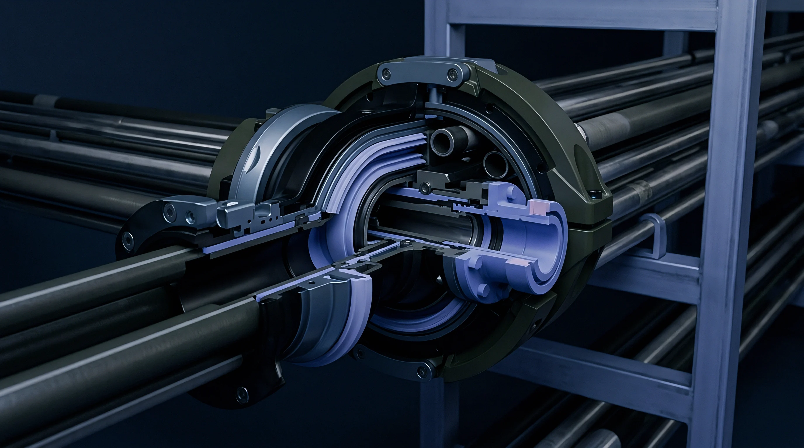
Tooling assemblies containing stacked manifold blocks require careful thermal isolation to prevent uncontrolled heat transfer between upper and lower distributor zones. Thermal isolation plates manufactured from glass-reinforced polyimide or titanium alloys isolate heated steel blocks from cold mold plates. Thermal sensors misread real gradients.
Without engineered isolation gaps, heat conducts rapidly into structural backing plates, establishing non-uniform thermal sink conditions across the manifold system.
Managing thermal expansion across multi-tier plates presents severe mechanical design constraints. As distributor blocks heat from room temperature to operating setpoints around 280°C, steel components expand expanding outwards from the central location pin. In non-symmetric multi-tier configurations, differential thermal expansion between upper distributor plates and lower manifold blocks misaligns nozzle drop centers if expansion vectors are calculated incorrectly.

Active Heating Zone Distribution for Tier Isolation
Heater element placement determines whether individual manifold blocks maintain uniform thermal profiles across varying cycle speeds. Operating multi-tier manifolds with single-zone control cards causes severe vertical thermal gradients, as natural convection drives heat upward into top-tier zones. Independent closed-loop temperature control across upper, middle, and lower distributor plates counteracts convective chimney effects inside the mold enclosure.
Placing heater cartridges in high-density configurations near cold structural drop locations maintains thermal stability. Sensor location is equally vital. Deeply embedded thermocouples positioned adjacent to flow channels provide accurate feedback for zone controllers, avoiding the thermal lagging effects observed when sensors are installed near outer steel faces.

Mechanical Expansion Compensation at Manifold Bushes
Differential thermal growth between the heated distributor block and the cold mould backing plate creates structural sealing challenges. Slide-fit drop bushes utilize pre-loaded spring stacks or precision-ground dowel interfaces to maintain sealing pressure across operating temperature ranges. Steel expands under elevated temperatures.
Tool steel selection dictates stability.
If an upper tier block operates at 275°C while a lower tier block operates at 255°C to compensate for shear heating, the differential thermal expansion between the two blocks reaches several hundredths of a millimeter. Toolmakers must incorporate floating dowel joints and sliding gate interfaces to absorb this relative motion without damaging alignment pins or inducing melt leakage at runner plate stack boundaries.
- Mount the primary distributor block onto central locating keys to fix the datum point for thermal growth.
- Install ceramic thermal insulation plates between manifold housing surfaces and mold clamping plates.
- Torque upper and lower tier heater band terminal connections to specified values to prevent resistance drift.
- Pre-heat the tool assembly to 150°C for two hours to allow uniform steel expansion prior to final drop alignment checks.
- Connect closed-loop zone controllers and verify thermocouple polarity for every independent tier circuit.
- Perform high-pressure seal testing using neutral color purging compound to confirm zero leakage at sliding splitter bushes.
| Component Component | Material Grade | Thermal Conductivity (W/m·K) | Expansion Coeff (10⁻⁶/K) | Max Operating Temp (°C) |
|---|---|---|---|---|
| Distributor Block | 1.2344 (H13) Steel | 24.5 | 11.8 | 450 |
| Splitter Bushing | Beryllium Copper Alloy | 210.0 | 17.0 | 300 |
| Isolation Plate | Woven Glass-Polyimide | 0.28 | 12.0 | 280 |
| Nozzle Tip Insert | Molybdenum TZM | 126.0 | 5.3 | 500 |
Specifying DIN 16742 Tolerance Group TG4 demands target drop temperature uniformity within plus or minus two degrees Celsius across all cavitation levels.
Positioning high-wattage heater cartridges near steel corners while maintaining dedicated zone controls for every level keeps thermal boundary shifts under control.
Validation
Verification of thermal and volumetric balance across multi-tier drops relies on systematic press-side monitoring and part quality audits. Melt front speeds become uneven. Mold trials must incorporate short-shot testing sequences to observe early cavity fill patterns under actual production conditions.
By progressively increasing injection volume from 50 percent to 95 percent of full part weight, technicians identify which drops fill prematurely due to elevated melt temperatures or lower flow resistance.
Laser surface thermography combined with melt pressure sensors installed behind ejector pins provides direct operational data on filling balance. Cavity pressure curves recorded across upper and lower tier cavities highlight differences in viscosity and gate freeze timing. If peak cavity pressure in lower tier cavities lags upper tier pressure by more than 5 percent, process engineers adjust individual zone setpoints to restore hydraulic equilibrium.
Drop Temperature Measurement and Pressure Tracing
In-cavity sensor arrays collect real-time data on pressure transfer rates and thermal arrivals across upper and lower mold levels. Direct melt temperature thermocouples positioned within nozzle drops measure the actual temperature of the polymer stream immediately before gate entry. These measurements reveal thermal shifts that thermocouple sensors buried deep in the steel manifold fail to register.
Integrating piezo-electric pressure transducers at the end of fill positions enables automated short-shot detection. If a lower-tier cavity demonstrates a slow pressure rise rate, the control system flags an imbalance driven by thermal memory decay or excessive heat loss along secondary channels. Analyzing these pressure traces across a 500-cycle stability trial establishes whether thermal coupling effects remain within stable process window limits.
Commercial Specifications for Multi-Tier Tool Sign-Off
The buyer embeds explicit cavitation balance thresholds before first steel sampling begins. Tool procurement documentation for non-symmetric multi-tier hot runner systems must include strict performance clauses governing volumetric fill balance and dimensional tolerances across all tiers. Standard acceptance criteria dictate that part weights across all cavities must fall within a total variation band of less than 1.2 percent when operating under nominal scientific molding process parameters.
Buyers should demand a multi-tier thermal audit dossier during tool sign-off. This document must record individual zone heater power consumption, internal melt temperature measurements at each drop, and part weight statistics calculated across five consecutive production runs. Tools failing to meet these thermal balance metrics transfer financial responsibility for manifold re-engineering back to the toolmaker.
Under section 4.2 of standard international tooling supply agreements, failure to achieve part weight uniformity within specified tolerances across all distributor tiers invalidates final tool acceptance and releases the buyer from final milestone payment obligations until runner re-balancing is completed.