Resolving Inline Wall Thickness Drift to Eliminate Conversion Mass Variances in Profile Extrusion
Inline mass drift is resolved by closed-loop gravimetric control and downstream ultrasonic wall tracking adjusting haul-off speed in real time.

Melt
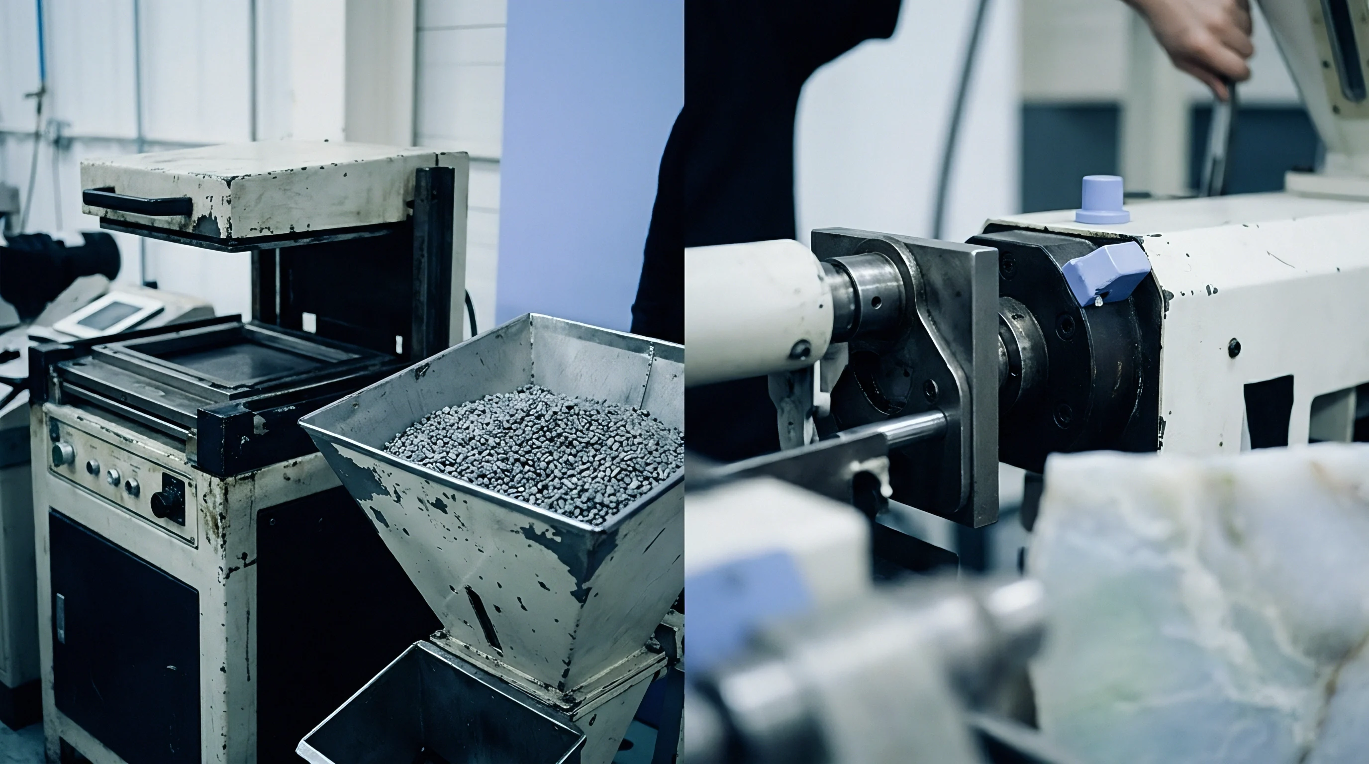
Extrusion pressure fluctuations at the breaker plate directly alter polymer throughput before material exits the shaping die orifice. When temperature zones along an extruder barrel drift by even two degrees Celsius, shear heating dynamics shift unpredictably. High-density polyethylene and unplasticized polyvinyl chloride exhibit distinct viscosity responses to these micro-thermal shifts.
Lower viscosity increases volumetric flow rate under constant screw speeds, expanding wall cross-sections prior to vacuum calibration. Conversely, cooler resin pockets increase hydraulic resistance, thinning profile walls below nominal specifications. Eliminating conversion mass variance requires arresting these internal fluid pressure oscillations at the extruder discharge.
Pressure stability depends on screw design, feed throat temperature consistency, and resin lot homogeneity. Double-flighted barrier screws separate molten polymer from un-melted pellets, reducing pressure pulsation at the tip. Without active pressure control, head pressure swings of three percent create downstream wall thickness variations exceeding five percent.
Melt pumps positioned between the barrel tip and die entrance serve as positive displacement meters, decoupling extruder surge from die head pressure. Synchronizing gear pump rotations with screw drive motors dampens high-frequency delivery ripples before extrudate contacts shaping steel.
Resin regrind ratios introduce chemical and molecular weight inconsistencies that destabilize melt flow indexes across single production shifts. Re-milled profile scrap possesses a lower intrinsic viscosity than virgin polymer due to prior thermal degradation cycles. Mixing twenty percent virgin material with un-sieved regrind creates fluctuating bulk density inside the hopper.
Bridging inside feed throat zones alters volumetric intake, forcing the drive motor to draw unstable amperage. These mechanical feed disruptions translate into periodic longitudinal wall thickness waves that ultrasonic sensors capture downstream.
Extruder melt pump installation reduces line pressure fluctuations from four percent down to less than one-half percent under steady-state operating conditions.
Pressure drives output.
Viscosity dictates resistance.
Extrudate swelling occurs immediately as molten polymer leaves the constraining land geometry of the die die-lip area. Relaxation of oriented polymer chains causes cross-sectional expansion, governed by first normal stress differences within the fluid. Polymer grades with broad molecular weight distributions show heightened swell, distorting wall ratios in complex profile geometries.
If interior webs swell faster than exterior perimeter walls, internal stress concentrates along corner radii, causing localized thinning. Regulating melt temperature precisely across die heat zones balances stress relaxation rates across asymmetrical profile sections.
| Parameter | Physical Mechanism | Wall Thickness Impact | Control Mechanism |
|---|---|---|---|
| Melt Temperature Drift | Viscosity change alters die resistance and volumetric rate | Higher heat yields thinner walls; lower heat swells walls | PID barrel zone tuning with closed-loop oil cooling |
| Head Pressure Surge | Screw feed instability drives erratic discharge volume | Longitudinal wall waves matching screw rotation frequency | Positive displacement melt pump placement before die |
| Bulk Density Variation | Hopper regrind stratifies virgin pellet feed packing | Unpredictable mass output variations over multi-hour runs | Loss-in-weight gravimetric dosing units at hopper inlet |
| Melt Swell Ratio | Normal stress relaxation upon die land exit | Dimensional growth in unsupported profile wall spans | Die land length elongation and drawdown ratio adjustment |
Equipment manufacturers frequently assert that modern twin-screw extruders eliminate the need for melt pumps through advanced barrel geometry alone. Processing engineers observe that raw material batch shifts still produce significant linear density deviations despite sophisticated screw profiles.

Sleeve
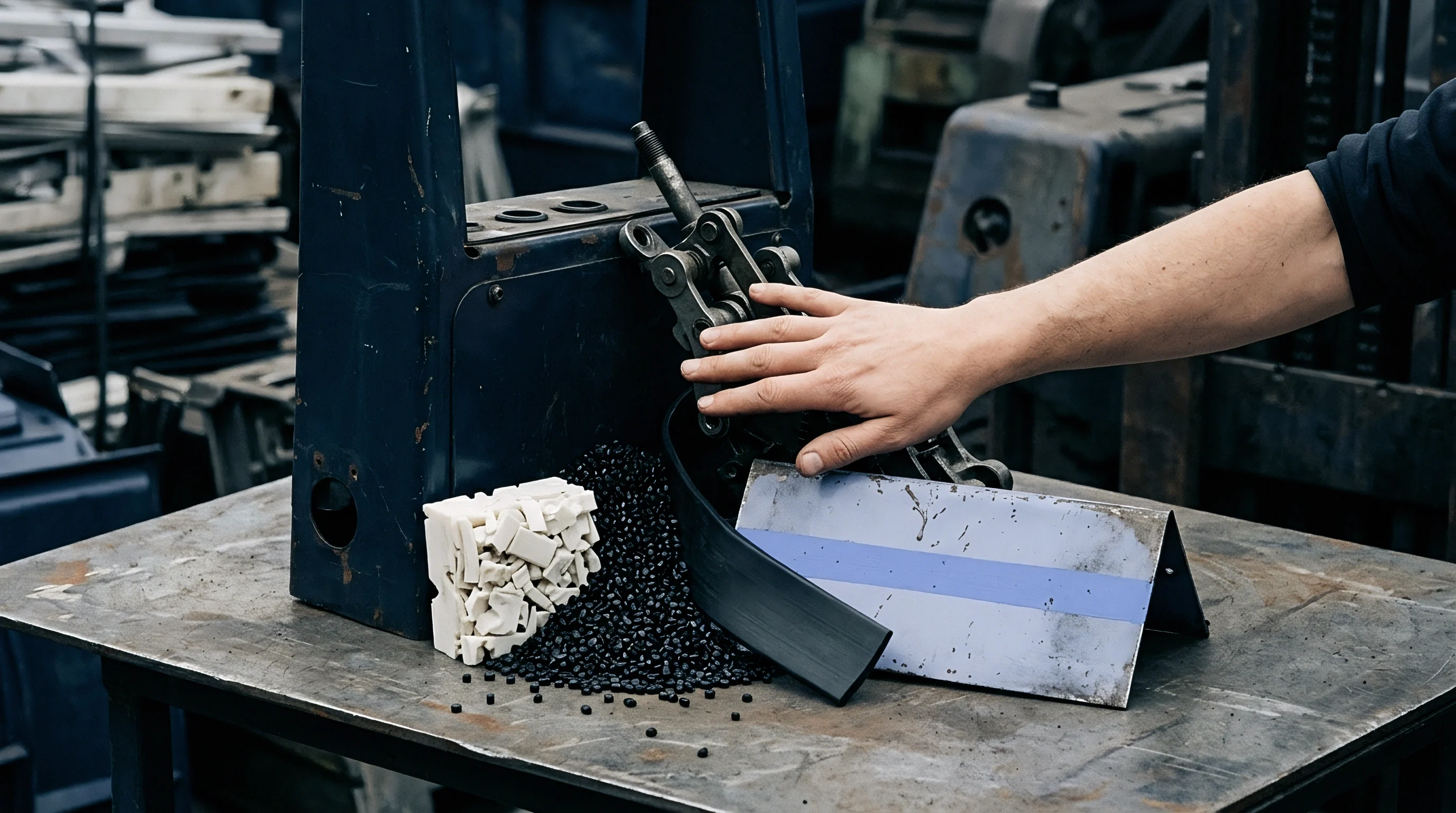
Vacuum calibration units define profile exterior dimensions through intense fluid contact and precise thermal extraction. Molten extrudate entering the calibration sleeve forms an exterior skin under continuous water vacuum pressure. Internal wall thickness depends on the balance between melt pressure pressing outward against the sleeve wall and puller tension drawing material forward.
If vacuum pressure drops below fifteen kilopascals, outer wall contact becomes intermittent, causing profile sag and localized mass accumulation. High vacuum levels increase frictional drag, inducing stick-slip motion that creates periodic transverse wall ripples.

Thermal Shrinkage Mechanics inside Calibration Tanks
Heat extraction rates inside wet calibration tanks dictate the solidifying boundary layer growth rate of semi-crystalline polymers. Polypropylene shrinks up to one and a half percent during initial cooling, whereas rigid PVC shrinks under one-half percent. High cooling rates freeze amorphous chains in un-relaxed states, trapping internal stresses that manifest later as post-extrusion profile warping.
Thick wall sections retain thermal energy longer than thin ribs, creating unequal shrinkage vectors across profile geometry. Water temperature variations of five degrees Celsius alter total volumetric shrinkage enough to shift linear weight outside specification limits.
Steel holds dimensions.
Calibrators control cooling rates.

Tooling Failures Driving Wall Thickness Drift
Extrusion die wear and calibration sleeve misalignments destroy cross-sectional mass stability over extended production campaigns. Over months of processing abrasive compounds filled with calcium carbonate, metal surfaces degrade along high-shear flow channels. Identifying mechanical root causes prevents fruitless adjustments to barrel processing temperatures.
- Die lip plate erosion opens mechanical flow paths preferentially along high-velocity center zones, starving thin outer profile leg sections.
- Calibration sleeve plate corrosion clogs internal vacuum slot apertures, reducing holding pressure and permitting outward wall bulging during cooling.
- Water jacket calcification restricts heat removal efficiency, elevating bath temperatures and extending the molten core zone down the line.
- Sizing pin eccentricity shifts internal mandrel alignments, producing profile walls that measure thick on top and thin underneath.
Water temperature alters shape.
Adjusting vacuum level rather than correcting physical die lip gap misalignments leads to unrecoverable stress accumulation within the cooling extrudate section.


Probe
Non-contact measurement stations sitting downstream of the cooling bath capture continuous wall dimensions across four spatial quadrants. Ultrasonic sensor arrays submersed in water tanks emit high-frequency acoustic pulses that reflect off profile outer and inner wall boundaries. Sound velocity through hot polymer varies with material density and temperature, requiring real-time calibration against known physical standards.
Terahertz wave technology provides dry measurement capability, penetrating opaque or multi-layer profiles without requiring a liquid acoustic coupling medium. Sensor response rates must exceed profile linear speed to capture rapid thickness surges.

Inline Gauging Integration Architecture
Continuous measurement systems convert raw sensor time-of-flight signals into instantaneous wall thickness profiles using digital signal processors. Array configurations place up to sixteen transducer elements around the profile periphery to detect circumferential asymmetry. When wall thickness strays beyond set control bands, the metrology system calculates linear density error vectors.
These vectors pass directly to the haul-off puller drive or melt pump control architecture to restore target dimensions before mass variances accumulate on the finished product spool.
- Position the ultrasonic sensor head inside the primary cooling bath immediately following the vacuum sizing unit where wall dimensions stabilize.
- Configure the polymer speed-of-sound calibration parameter using an offline ultrasonic sample block heated to sixty degrees Celsius.
- Establish spatial orientation coordinates aligning transducer beam paths perpendicular to profile outer wall surfaces within one degree.
- Set measurement sample averaging filters to record twenty spatial readings per second to eliminate mechanical line vibration noise.
- Verify real-time readings against destructive micrometer cuts taken from end-of-run profile samples twice per shift.
Under EN 12201 structural profile guidelines, continuous wall thickness tracking must maintain dimensional variance within plus or minus three percent of nominal wall limits.
Sound waves measure wall thickness.
Friction retards advancement.
Optical laser triangulation systems supplement acoustic probes when inspecting complex open-profile geometries. Twin laser heads project lines across exterior ribs, computing wall thickness through coordinate math relative to an internal mechanical mandrel position. Dark pigments and carbon black loading absorb optical wavelengths, requiring increased laser diode output or infrared spectrum sensors.
Signal attenuation in dense compounds limits optical depth penetration on thick structural walls. Combining acoustic and optical inspection techniques provides full profile coverage regardless of resin opacity or internal void structures.
Can multi-frequency terahertz array sensors maintain measurement stability on high-filler calcium carbonate profiles running at linear speeds exceeding twenty meters per minute?

Traction
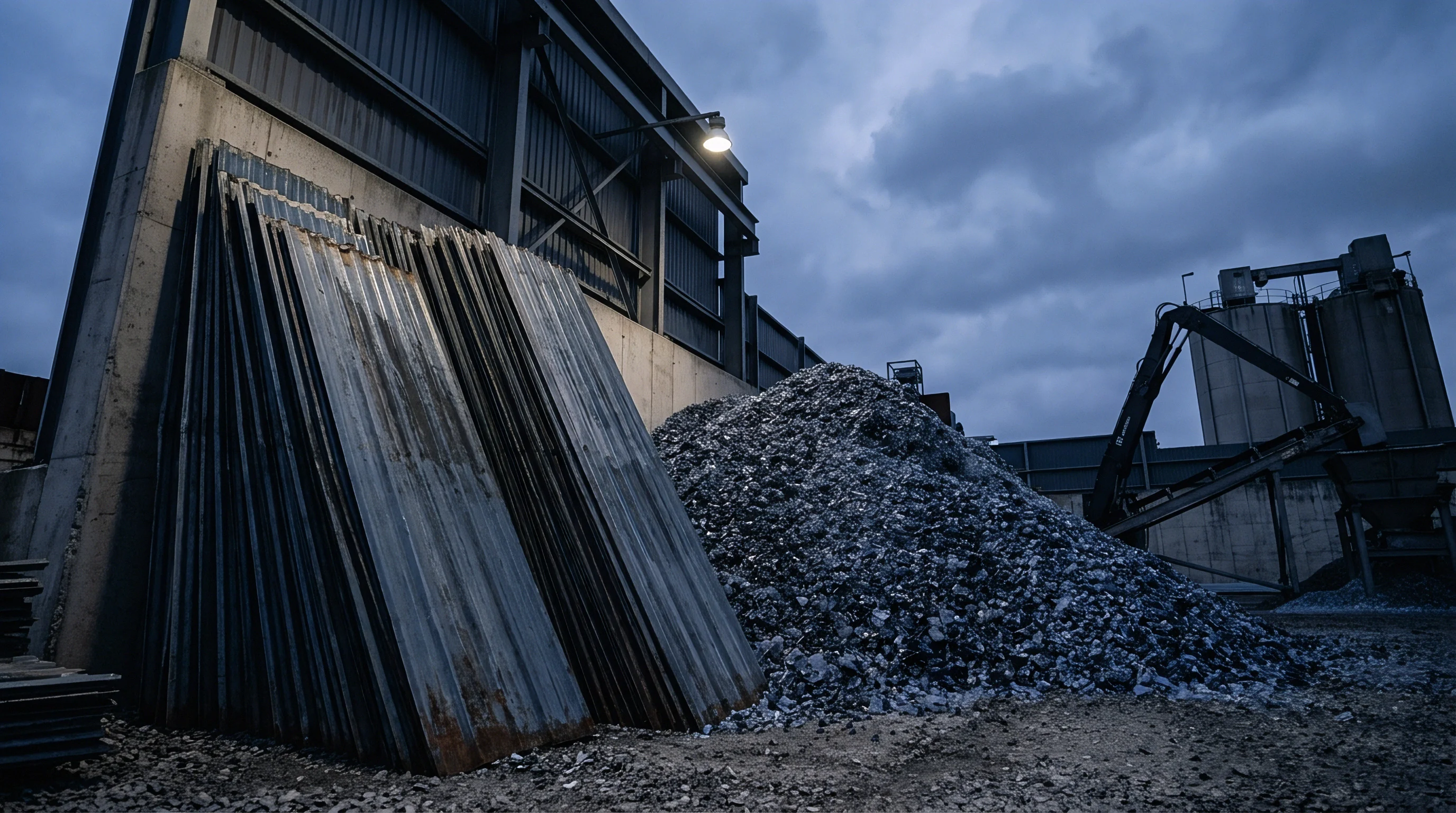
Belt pullers deliver linear velocity to cooled profiles, pulling extrudate through shaping dies under continuous mechanical tension. Slippage between puller belts and profile surfaces alters drawdown ratios, thinning wall sections during speed spikes and thickening walls during belt hesitation. Pneumatic belt clamping pressure must overcome line friction without crushing hollow interior profile chambers.
Polyurethane belt pads with sixty Shore A hardness supply sufficient traction against wet profile surfaces without leaving mechanical clamping marks on show surfaces.
Which Haul off Feedback Loops Eliminate Wall Mass Variance?
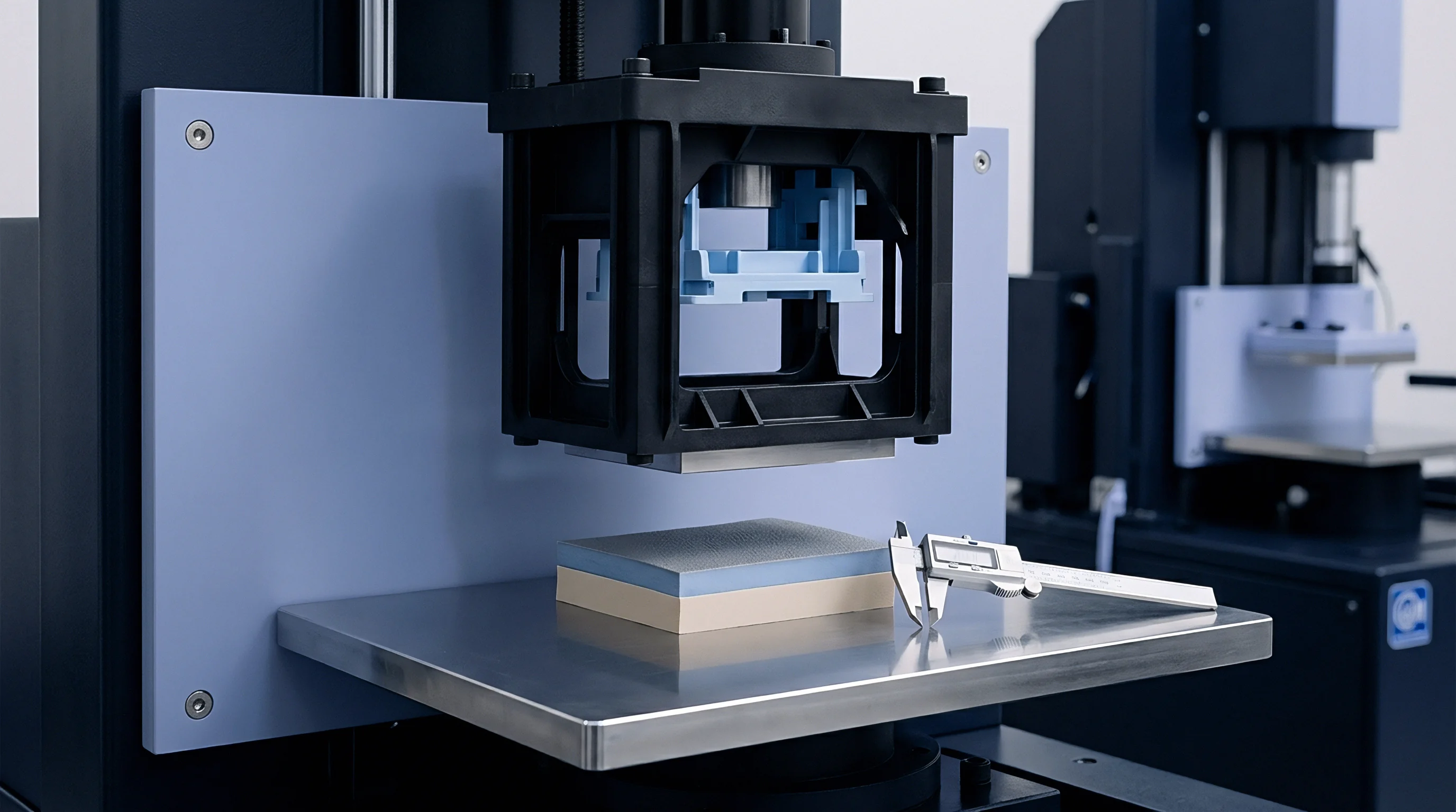
Integrating gravimetric extruder control with puller encoder feedback compensates for density swings during continuous operations. Loss-in-weight hopper systems measure total resin mass entering the extruder barrel per unit time. If resin feed rate decreases by two percent, the gravimetric controller sends an analog signal slowing the puller belt speed proportionately.
This continuous line speed modulation preserves constant linear profile weight (grams per meter) despite hopper feed instability or bulk density shifts.
Encoders track belt displacement.
Speed variations stretch extrudate.
Drive motor selection dictates speed regulation precision across wide speed ranges. AC vector drives paired with high-resolution optical encoders hold rotational speed within one hundredth of one percent under variable line load conditions. Older DC drive systems display thermal drift as motor windings heat up during extended production runs, introducing slow-wave wall thickness drift across shift changes.
Direct-drive servo motors eliminate gearbox backlash, preventing high-frequency speed hunting that creates microscopic thickness ridges along extruded profile walls.
Controlling linear density via gravimetric line speed integration yields tighter mass distributions than manual screw speed adjustments.
Failing to synchronize puller speed adjustments with extruder output changes results in severe wall thinning, leading to catastrophic structural collapse under load testing.

Batch
Quality records logging linear density demonstrate whether continuous profile runs satisfy dimensional agreements across full production lots. Statistical process control charts track nominal wall thickness averages alongside process capability indexes (Cpk). Maintaining a Cpk above 1.33 demands that natural wall variation spans less than seventy-five percent of allowable tolerance windows.
When wall variation strays beyond upper control limits, conversion mass increases, burning un-budgeted raw material money. Lower control limit breaches result in thin structural walls that fail impact or hydrostatic pressure testing.
| Tolerance Grade | Nominal Wall Range (mm) | Allowable Wall Drift (mm) | Linear Mass Variance Limit (%) | Primary Application |
|---|---|---|---|---|
| DIN 16742 TG3 | 1.0 to 3.0 | +/- 0.08 | +/- 2.5 | Precision medical micro-tubing and technical profiles |
| DIN 16742 TG5 | 3.0 to 6.0 | +/- 0.15 | +/- 4.0 | Architectural window frames and structural trim profiles |
| DIN 16742 TG7 | 6.0 to 12.0 | +/- 0.30 | +/- 6.5 | Heavy industrial fluid conduits and cable trunking |
| ISO 2768-m | 2.0 to 8.0 | +/- 0.20 | +/- 5.0 | General commercial building gaskets and edge seals |
Tooling wear opens flow gaps.
Linear mass governs resin costs.
Acceptance sampling procedures require statistical validation across entire production runs before lot release. Destructive cross-sectional optical comparator measurements verify inline acoustic probe calibration data. Samples taken at thirty-minute intervals confirm whether thermal equilibrium persisted across shift changes.
When automated inline systems log thickness excursions lasting longer than forty seconds, line operators tag that profile length for quarantine and rework sorting.
Under ISO 20753 quality compliance provisions, lot documentation must record both minimum wall thickness values and total linear conversion mass to ensure structural material integrity across long-term supply agreements.


Yield
Extruding profiles beyond minimum structural wall targets consumes excess resin that directly diminishes conversion profit margins. Sourcing agreements define profile pricing based on nominal weight per meter multiplied by total production length. When process instability forces production teams to run profiles overweight to guarantee minimum wall compliance, resin consumption spikes.
Eliminating wall thickness drift allows process engineers to move target wall settings closer to lower engineering tolerance boundaries, harvesting significant raw material savings.

Worked Conversion Mass Financial Calculation
Evaluating the commercial impact of wall drift reduction requires modeling raw material consumption over a standard production run. Assume a production line runs rigid PVC profile at a line speed of twelve meters per minute for five thousand operating hours annually. Nominal profile specification targets a mass of 450 grams per meter, corresponding to a nominal wall thickness of 2.50 millimeters.
Material cost sits at 1.45 USD per kilogram.
Slight variations multiply over distance.
Without inline closed-loop control, wall thickness drift averages plus or minus 0.15 millimeters (six percent variance). To prevent thin-wall non-compliance below the 2.35 millimeter absolute limit, operators set nominal line running targets at 2.60 millimeters (468 grams per meter). Operating eighteen grams per meter overweight over 3.6 million annual production meters consumes an additional 64,800 kilograms of resin.
This process bias adds 93,960 USD in unrecoverable raw material expenditure every year on a single extrusion line.
Implementing ultrasonic inline gauging coupled with gravimetric closed-loop puller speed control reduces wall thickness variation to plus or minus 0.03 millimeters. Process control stability enables shifting the target operating point down to 2.38 millimeters (428.4 grams per meter) while staying strictly above the 2.35 millimeter specification limit. Total annual resin consumption drops to 1,542,240 kilograms, saving 77,220 USD in material costs compared to nominal target running, and over 171,000 USD compared to the un-controlled overweight baseline setup.
Overweight profiles consume profits.
Data guides line speed changes.
Reducing wall thickness variability by four percent on a high-throughput extrusion line pays back total closed-loop gauging hardware investments within seven months of operation.
Achieving stable conversion yield links mechanical process capability directly to financial profitability. Process controls that eliminate wall drift ensure that resin purchased at the feed throat matches the mass shipped to customers on finished reels.