Extrusion Blow Moulding Parison Programming and Wall Thickness Calibration
Dynamic die gap programming aligns parison mass with mould draw ratios, stripping container resin weight while locking required structural wall minimums.
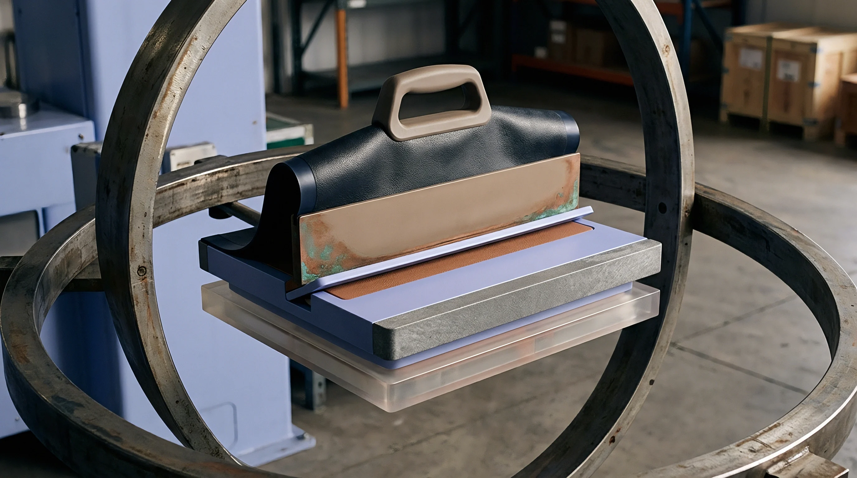

Die
Tooling geometry inside an extrusion blow moulding head sets the initial cross-sectional velocity of the polymer before gravity and air alter the melt. Converging tooling geometries compress the flowing plastic inward toward the central axis as the melt exits the annular gap between the core pin and the die bush. Diverging tooling turns the polymer outward, inducing tensile radial stress that changes how the free melt tube expands upon clearing the steel face.
Toolmakers machine these components from heat-treated H13 tool steel or beryllium-copper alloys to resist abrasive wear from pigment masterbatches and high-density polyethylene melts running at stock temperatures between 180 and 210 degrees Celsius.
The gap between the mandrel and the die orifice establishes the base parison wall thickness before servo actuators apply dynamic positioning. A fixed orifice produces a uniform tube when processing simple cylinders. Asymmetrical containers demand profiled tooling.
Ovalization of the die bush or mandrel introduces intentional circumference-dependent thickness variations, feeding additional material into mould corners that undergo the severe draw ratios of deep rectangular geometries.
A die gap clearance of 1.2 millimeters produces a post-swell parison shell averaging 2.4 millimeters when extruding high-molecular-weight polyethylene at 195 degrees Celsius.
Toolroom practice machines ovalized lands with electrical discharge machining electrodes matched to container aspect ratios. Tool steel cut with a thirty percent radial relief along the narrow mould axis delivers material directly to the bottle shoulders during clamping. Symmetrical round tooling run on square containers starves the outer corners of melt, causing premature container failure during drop tests.
The physical entry angle of the die head channel also governs backpressure; converging entry angles exceeding forty-five degrees generate excessive melt fracture, disrupting laminar parison flow.

Mandrel Geometry and Melt Pressure
Flow channels within accumulator heads or continuous extrusion heads divide the pressurized polymer around spider legs or feed it through spiral mandrel distributors. Spiral distributors eliminate structural knit lines by overlapping multiple melt streams, creating uniform radial pressure across the entire annular exit. Spider leg configurations split the melt stream mechanically, leaving molecular knit lines downstream of each support fin.
These knit lines manifest as localized zones of altered crystallinity and lower burst strength.
Mould builders compensate for shear heating within the tooling by integrating independent multi-zone band heaters along the head body. Temperature differentials across the die circumference generate differential melt flow rates, leading to parison curtaining where the extruded tube bows toward the hotter tooling quadrant. The press operator remedies curtaining by balancing thermal zones across four quadrants within plus or minus 1.5 degrees Celsius.
Moulders frequently attribute parison curvature and regional thinning to resin batch contamination rather than admitting thermal gradient drift across uncalibrated die head ceramic band heaters.


Swell
Polymer molecules deform elastically as extruder flights compress them through restricted tooling passages. Exiting the constrained annular die land allows these coiled macromolecular chains to recoil, expanding parison wall thickness while reducing total tube length. High-density polyethylene exhibits diametrical swell ratios between 1.2 and 1.8, accompanied by weight swell ratios reaching 2.2 under severe extrusion shear rates.
This elastic memory complicates digital programming by decoupling tool gap dimensions from final container wall distributions.
Extrusion velocity heavily influences the magnitude of elastic recovery. High screw revolutions per minute reduce residence time inside the die land, preventing molecular relaxation and magnifying post-extrusion expansion. Accumulator head machines pushing fifty kilograms of melt through the tooling within three seconds generate high instantaneous shear stresses, producing radical diametrical bloom.
Continuous extrusion heads operate at lower, steady-state shear rates, yielding lower swell factors that remain predictable across long manufacturing shifts.
Resin molecular architecture governs this recovery behavior. Broad molecular weight distributions contain long polymer chains that store elastic strain energy effectively. Fractional melt flow index blow moulding grades, exhibiting melt flow rates below 0.35 grams per ten minutes under 2.16-kilogram loads at 190 degrees Celsius, demonstrate pronounced swell.
Processing identical bottle geometries using narrower distribution resins reduces swell, dropping corner thickness and necessitating tooling gap recalibration.
Viscoelastic recovery expands the parison outward while shortening suspended vertical length before the blow mould closes.

Viscoelastic Relaxation Dynamics
Molecular weight distribution also determines how rapidly the extruded tube sags under its own mass during continuous extrusion cycles. Parison sag acts in opposition to diameter swell, stretching the upper sections of the hanging tube while the lower section rests unconstrained. The time spent hanging in open air between extrusion and mould closure defines the net draw ratio of the uninflated tube.
The following process variables interact directly to dictate real-time parison geometry before mould pinch-off:
- Extrusion melt temperature alters polymer relaxation times, causing hotter parisons to sag rapidly while cooler tubes retain elastic die memory.
- Die land length provides residence time under shear, where longer lands allow molecular orientation relaxation that decreases radial swelling at the tool exit.
- Suspension drop time dictates total gravitational draw down, stretching upper container wall stock when cycle times extend beyond targeted baselines.
- Blow-up ratio calculates the quotient of maximum mould cavity diameter divided by parison diameter, setting absolute boundary limits for corner stretching.
A higher blow-up ratio demands heavier parison programming intervention along the vertical axis. Ratios exceeding 3.5 to 1 strip thickness away from container parting lines, generating pinholes during high-pressure inflation. Die tooling diameters require selection that keeps nominal blow-up ratios within a manageable 1.8 to 2.5 envelope.
Thick parisons maintain core heat longer, while thin walls freeze against cold steel before complete structural packing occurs.
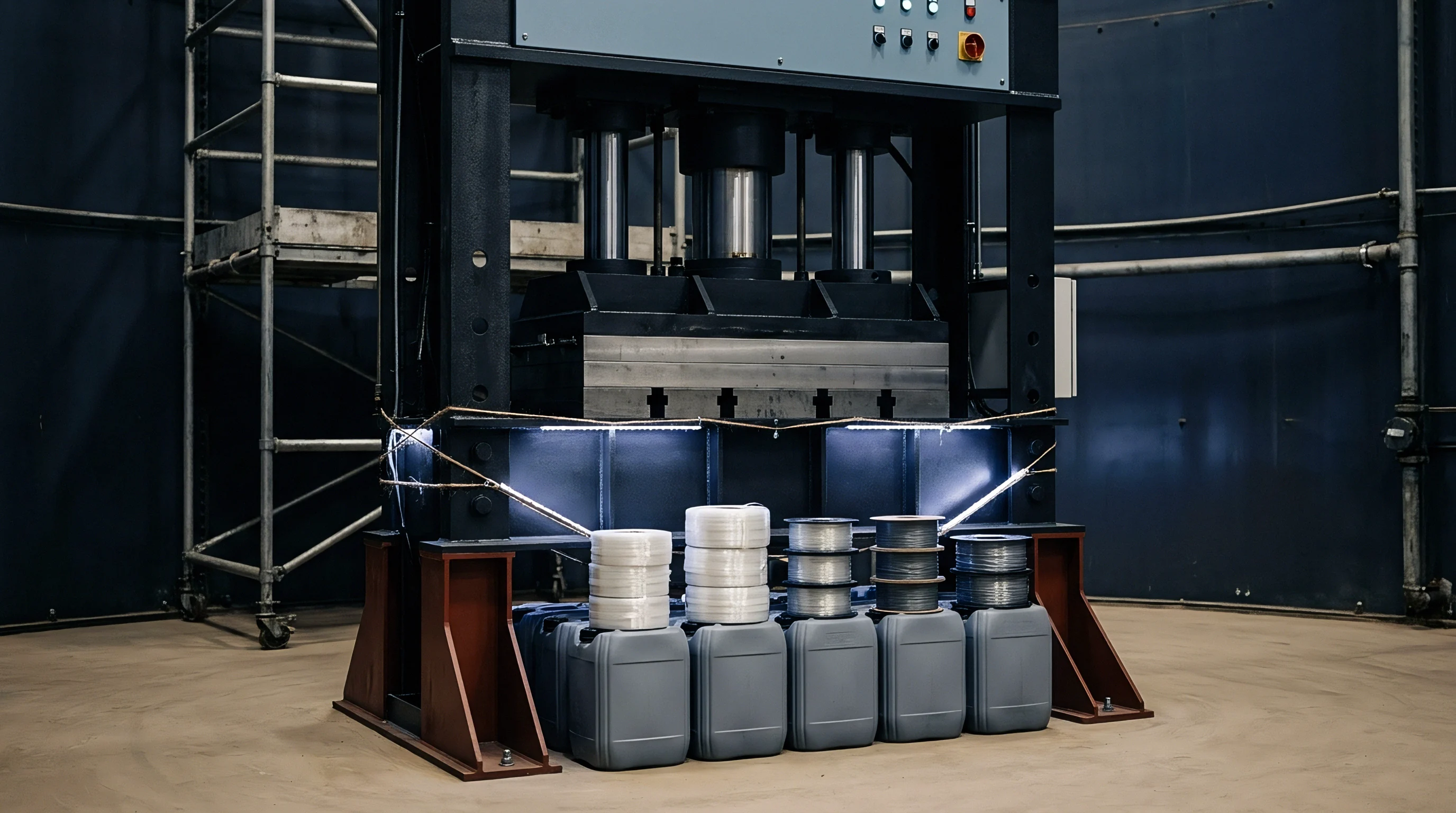

Servo
Dynamic parison programming modulates the annular gap in real time as the melt tube descends from the die face. High-speed hydraulic proportional valves or electric servo actuators translate the central mandrel along its vertical axis, widening or narrowing the die clearance across predefined profile segments. Standard digital controllers divide the total extruded parison length into sixty-four, one hundred, or four hundred discrete programming points.
The machine assigns an independent opening percentage to each increment, profiling the vertical wall stock to match the shape of the incoming mould cavity.
Actuator responsiveness sets physical limits on profile sharp transitions. A programming profile commanding an instant jump from twenty percent to eighty percent gap opening over three interpolation points cannot be physically realized by high-tonnage tooling cores. Mechanical inertia of the heavy steel mandrel, coupled with hydraulic oil compressibility, limits dynamic responsiveness.
The physical gap change rounds off sharp programmatic transitions, producing a smoothed exponential ramp across the moving polymer parison.

What Governs Dynamic Tooling Gap Response?
Hydraulic servo systems rely on closed-loop linear variable differential transformers mounted directly to the die tooling stem. Modern all-electric heads replace hydraulic cylinders with zero-backlash ball screws driven by brushless AC servomotors, achieving positioning repeatability within 0.005 millimeters. This physical accuracy enables precise placement of localized material bands, thickening the parison exactly where container handles, internal vacuum panels, or bottom push-up recesses draw down the melt.
The operational sequence for establishing a calibrated profile follows an exacting technical progression:
- Dry cycle the accumulator or continuous head to map mechanical home positions using calibrated dial indicators on the core pin.
- Extrude unprofiled, straight-gap parisons to establish baseline part weights and record total unconstrained cycle drop times across five test cycles.
- Program stepped thickness pulses of twenty percent amplitude at twenty-point intervals along the controller interpolation curve.
- Catch and quench the striped parison in cold water to visually correlate controller screen coordinate percentages with physical vertical locations along the tube.
- Adjust profile points adjacent to the handle flash and bottom pinch-off to starve pinch zones while packing high-draw container corners.
- Lock controller loop gains to prevent servo oscillation caused by hydraulic valve temperature drift across continuous shifts.
Servo hunting introduces cyclical parison thickness rings, visible as horizontal ridges along the finished product body. Stiffening the proportional gain too far causes mechanical shudder in the die head support frame, accelerating mechanical wear on mandrel guide bushings.
| Profile Point Band | Target Container Zone | Programmed Gap (%) | Physical Gap (mm) | Blow Ratio |
|---|---|---|---|---|
| Points 01-15 | Bottom Pinch-Off and Chime | 32 | 1.28 | 1.45:1 |
| Points 16-45 | Lower Body and Bumper Ring | 48 | 1.92 | 2.10:1 |
| Points 46-68 | Main Wall Panels | 26 | 1.04 | 1.60:1 |
| Points 69-85 | Shoulder and Integrated Handle | 74 | 2.96 | 3.40:1 |
| Points 86-100 | Container Neck and Thread Finish | 42 | 1.68 | 1.15:1 |
Digital gap programming coordinates directly with the cycle timer of the clamping unit. If parison drop velocity varies due to extruder screw speed hunting, the physical position of the thickness bands shifts relative to the closing mould cavities. Machine controls mitigate this by coupling parison programming to optical drop sensors or extruder screw tachometers, syncing programming slices to actual extruded melt length rather than elapsed wall-clock seconds.
Whether closed-loop optical tracking of parison swell can entirely replace manual profile point calibration remains unresolved in automated continuous production environments.

Pinch
Mould closing forces weld the extruded tube at the container base and neck, sealing the parison against pressurized air injection. Pinch-off inserts, machined from hardened tool steel or AMPCO beryllium-copper alloys, feature precise land widths and relief angles. The steel land compresses the hot melt without cutting it through prematurely before molecular cohesion occurs across the parting line.
A pinch land that is excessively sharp severs polymer chains instantly, producing brittle, notched bottom welds that fail drop testing under minimal liquid impact loads.
The standard pinch geometry utilizes a flat land width between 0.5 and 1.5 millimeters, leading back into a thirty-degree relief pocket. This relief cavity accommodates excess displaced polymer, known as flash. The molten polymer must flow smoothly into the flash pocket while maintaining continuous hydraulic backpressure against the weld joint.
Insufficient relief pocket volume traps cold flash against the mould parting face, holding the main cavity faces apart and creating out-of-tolerance container seams.
A pinch land narrower than 0.4 millimeters acts as an internal shear knife, destroying impact resistance along the container base seam.
Cooling channel placement inside pinch inserts governs weld crystallographic morphology. Slower cooling around the bottom weld promotes brittle spherulitic crystal structures in high-density polyethylene, weakening the seam. Directed water circuits delivering coolant at twelve degrees Celsius directly beneath pinch lands freeze the weld rapidly, promoting amorphous structures characterized by high tensile toughness and drop endurance.
Flash dam structures built into pinch inserts control the extrusion of excess melt into the handle openings of industrial containers. The flash dam creates a targeted flow restriction, forcing parison melt into deep cavity corners before sealing the handle waste slug. Incorrect dam heights leave web flash inside handles, demanding high manual trimming labor or causing jam-ups in downstream automated deflashing machinery.
Neglecting pinch insert wear leads to thick, structural flash skirts that jam automated conveyor transfer systems and split container seams during pallet stacking.

Metrology
Destructive sectioning and non-destructive gauging determine whether parison programming achieves engineering drawing requirements. Continuous process monitoring relies on magnetic hall-effect thickness gauges and multi-axis ultrasonic sensors to verify wall thickness profiles across high-stress zones. Ultrasonic inspection measures the transit time of high-frequency acoustic pulses traversing the polymer matrix, calculating wall thickness directly when calibrated to the specific acoustic velocity of the polymer grade.
High-density polyethylene exhibits an acoustic velocity near 2,200 meters per second at room temperature. Measuring hot containers directly at the press requires temperature compensation curves, because sound velocity decreases systematically as polymer temperature rises. Technicians track measurement drift by maintaining dedicated cooling water baths, stabilizing extracted parts at twenty-three degrees Celsius before taking quality audit records.
| Container Nominal Capacity | Nominal Wall (mm) | Minimum Wall Limit (mm) | Permissible Variance | Target Process Cpk |
|---|---|---|---|---|
| 250 ml to 500 ml | 0.80 | 0.55 | ±0.15 mm | 1.33 |
| 1 Liter to 2 Liter | 1.10 | 0.75 | ±0.20 mm | 1.33 |
| 5 Liter Round | 1.45 | 0.95 | ±0.25 mm | 1.67 |
| 5 Liter Handled Jerrycan | 1.65 | 1.05 | ±0.30 mm | 1.33 |
| 20 Liter Industrial Drum | 2.80 | 1.85 | ±0.45 mm | 1.67 |
Destructive bottle cutting protocols isolate critical evaluation zones: the container base chime, the lower bumper ring, the label panel center, the bottle shoulder, and the neck finish parting line. Operators punch disk samples from cut sections, checking regional mass distribution on precision balances to confirm parison programming matches theoretical volumetric allocations.
Container dimensional compliance must satisfy geometric criteria established in DIN 16742, which standardizes permissible deviations for hollow plastic bodies formed without internal mould cores. Quality departments reject incoming production lots whenever ultrasonic wall scanning detects localized thinning below the minimum design threshold defined in product performance dossiers.
Container failure analysis traces mechanical defects back to specific process origins using rigorous physical indicators:
- Brittle bottom drop failure originates from excessively cold mould pinch inserts or oversized pinch land widths exceeding 1.8 millimeters.
- Corner panel collapse points to insufficient parison programming thickness points or excessive blow-up ratios across deep rectangular profiles.
- Circumferential parison banding reveals hydraulic valve hunting or uncalibrated proportional servo feedback cards on the tooling carriage.
- Vertical wall thickness asymmetry marks misaligned die tooling, uneven die head heater bands, or parison draft deflection caused by mold enclosure air drafts.
Purchase contracts governed by standard quality clauses stipulate that wall thickness falling below ninety percent of drawing nominal invalidates lot acceptance, passing full sorting and disposal costs back to the moulding facility.
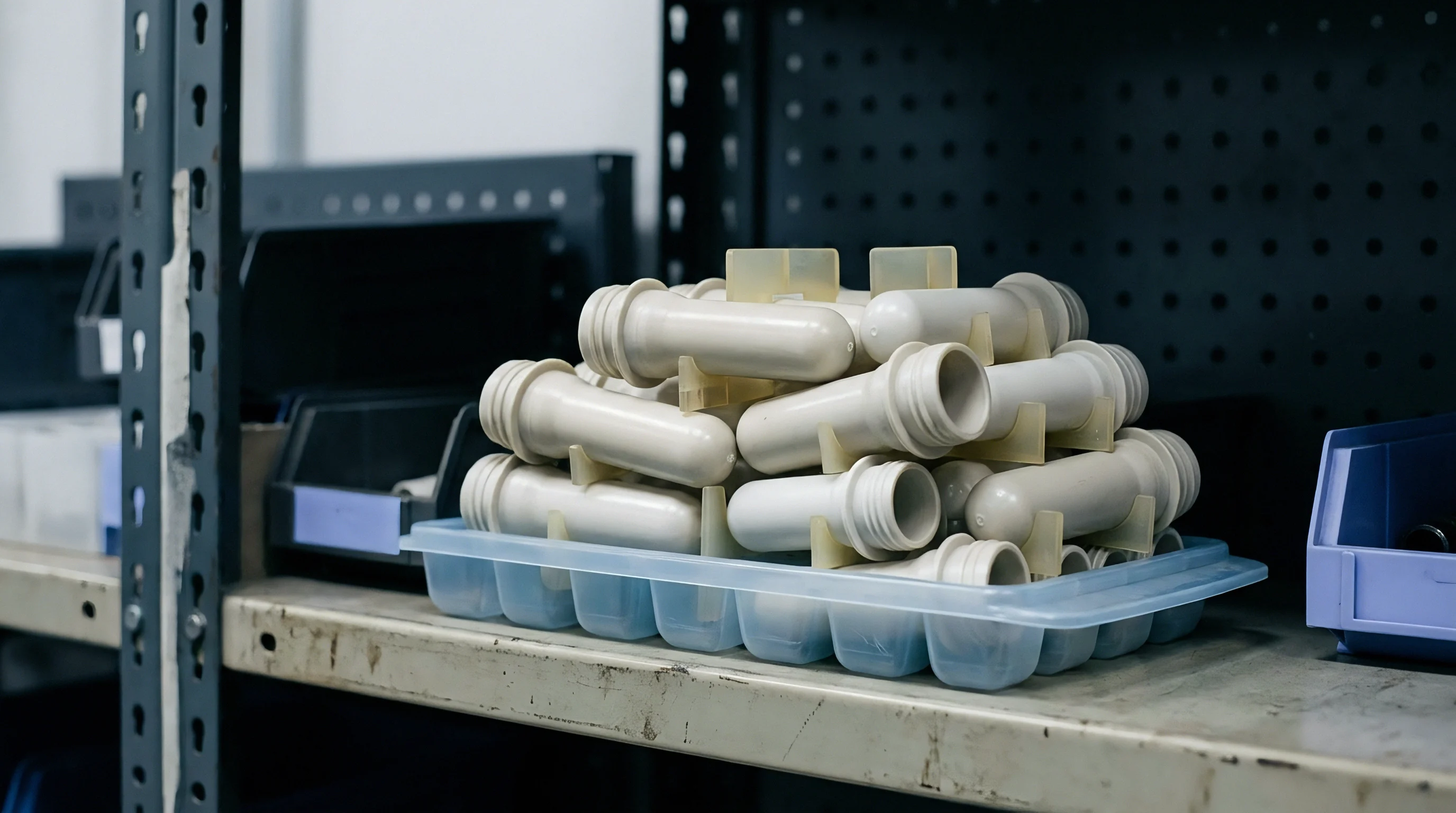
Ledger
Parison programming efficiency directly dictates the commercial profitability of high-volume blow moulding programs. Plastic resin accounts for sixty to seventy percent of the landed manufacturing cost of a typical hollow container. Running an uncalibrated parison profile forces technicians to increase overall bottle target weight by ten to fifteen percent to protect the thinnest corner from dropping below structural drop-impact specifications.
Calibrating the servo program distributes material away from low-stress flat walls into vulnerable corners, stripping unnecessary resin weight out of every shot.
A production calculation illustrates the commercial stakes of programming optimization. Take a continuous four-cavity wheel machine producing five-liter industrial containers at an output rate of 1,800 units per hour, operating 6,000 hours annually. Total production volume reaches 10,800,000 bottles per year.
Assume a virgin high-density polyethylene resin cost of 1.45 dollars per kilogram. Running an unoptimized baseline parison yields a finished bottle weighing 185 grams, meeting minimum corner thickness limits of 0.85 millimeters through raw material saturation.
Deploying a calibrated one-hundred-point servo program shapes the parison profile, increasing gap opening along the bottle handle while narrowing the die clearance across the main label panels. This optimization lowers bottle weight to 168 grams while sustaining the required 0.85-millimeter minimum wall limit at every corner. The process strips seventeen grams of plastic from each unit.
Annual resin consumption drops from 1,998 metric tons to 1,814.4 metric tons. Net raw material savings total 183.6 metric tons of resin annually. At 1.45 dollars per kilogram, this single calibration effort captures 266,220 dollars in direct bottom-line material cost recovery per machine line each year.
Tooling wear decreases concurrently, as reducing parison wall thickness lowers required clamp tonnage, minimizing mechanical fatigue across mould guide pins and parting surfaces.
Cycle times shrink alongside parison weight reduction. Thick wall sections act as thermal insulators; high-density polyethylene transfers heat outward at a modest thermal conductivity rate of 0.44 watts per meter Kelvin. Cooling time scales proportionally with the square of the maximum wall thickness.
Trimming a 2.8-millimeter handle pinch zone down to 2.1 millimeters drops required in-mould cooling dwell by 2.4 seconds per machine cycle. Across high-volume annual operational schedules, that cycle compression unlocks substantial additional machine cavitation capacity without committing capital to additional steel tooling.