Multi Cavity Tool Signal Wiring and Junction Isolation Architecture
Ruggedized raceways, continuous isolation barriers, and single-point grounding eliminate thermal noise and ground loops in high-cavitation tooling.

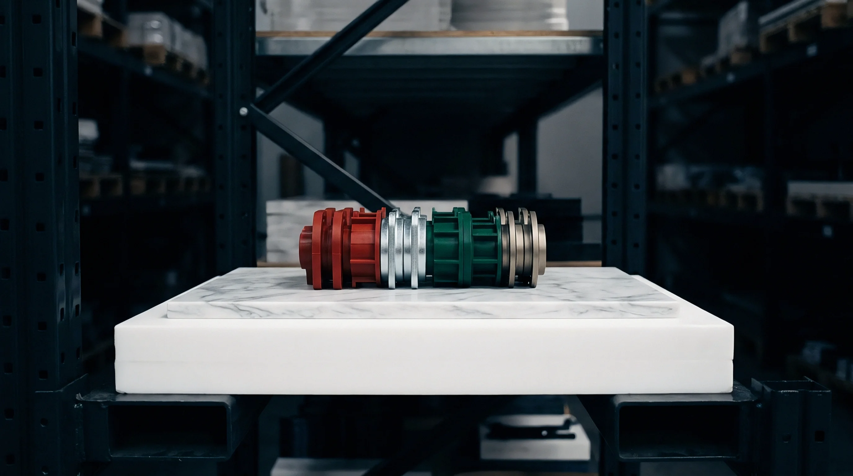
Conduit
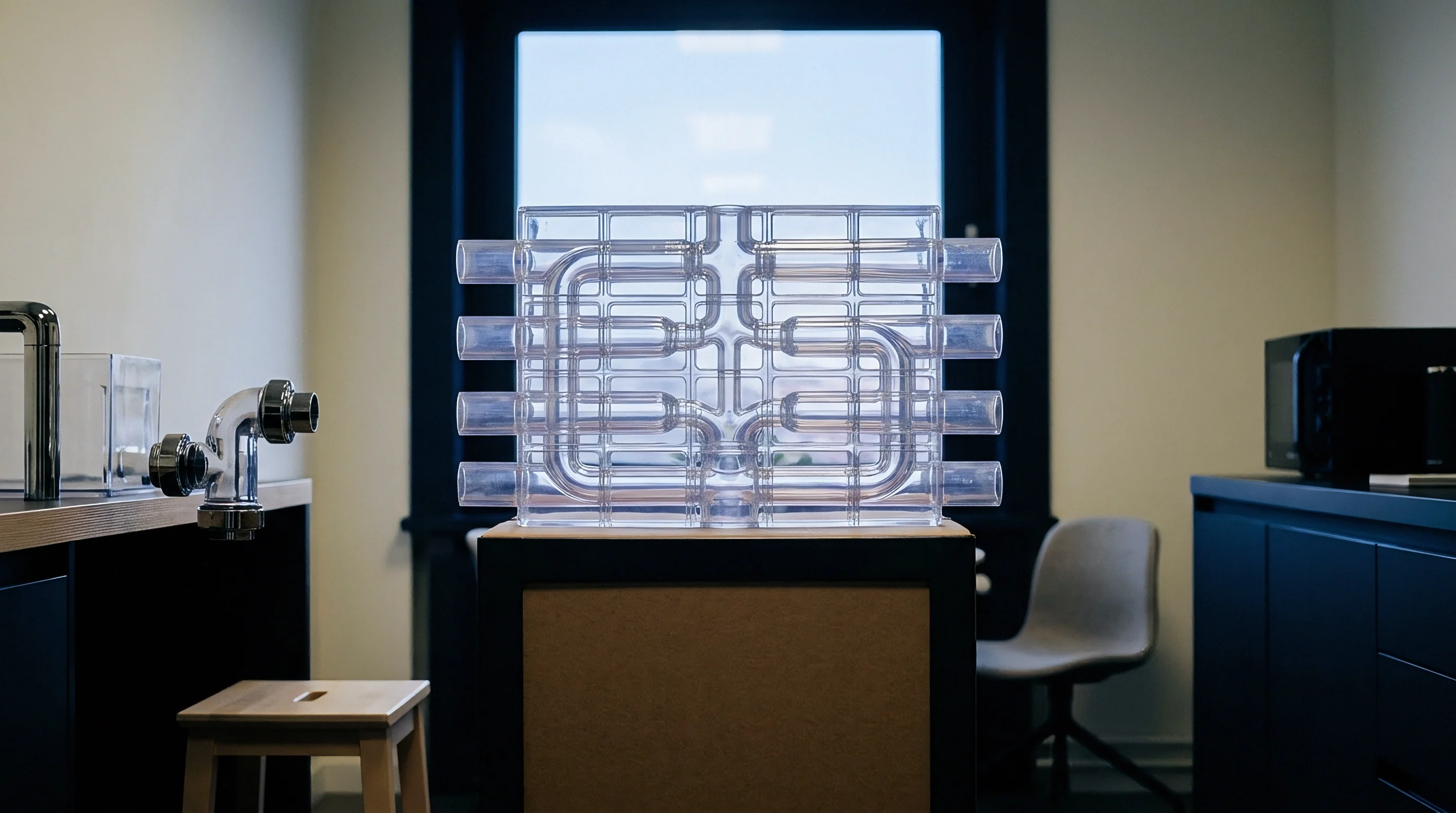
Routing Geometries and Mechanical Protection
Signal corruption in multi-cavity injection moulds originates inside mechanical raceways long before charge amplifiers see electrical noise. Cavity pressure sensors utilizing piezoelectric quartz crystals generate pico-coulomb charge packets. A typical 0 to 2000 bar transducer yields between minus 2.0 and minus 4.5 pico-coulombs per bar.
High-impedance lines carrying these packets through an injection mould plate encounter 200-tonne cyclic clamping loads, hydraulic pulses, and conductive particulate from slide wear. Routing channels milled into the back of cavity retainer plates isolate transducers from mechanical pinch points and thermal gradients.
Machined raceways demand a minimum radius of 25 millimetres on all 90-degree turns to preserve the structural integrity of miniature low-noise coaxial cables. A PTFE-jacketed cable crushed beyond its specified elastic deformation threshold suffers dielectric breakdown and triboelectric noise generation. When cables vibrate against bare steel raceway walls during machine acceleration, frictional contact generates static potentials exceeding 50 millivolts across the amplifier terminals, swamping micro-charge readings.
Raceways cut into the B-plate require clamped aluminium retaining strips spaced every 75 millimetres. These clips prevent cable flotation into the parting line during tool assembly or maintenance cycles.
A minimum bending radius of twenty-five millimetres preserves low-noise coaxial dielectric layers against cyclic vibration during machine clamp-up.
Drilled gun-drill intersecting conduits present burrs that shear braided copper shields during harness pulls. Toolrooms address this failure mode by chamfering internal junction intersections using thermal deburring or abrasive flow machining. An unchamfered intersection cuts the secondary outer fluoropolymer sheath, creating an intermittent grounding condition against the mould base.
Once a cable braid touches tool steel at multiple unmonitored points, circulating ground loops destroy the baseline reference of the data acquisition system.
Plate Separation and Thermal Boundaries
Thermal management across tool plates directly controls the signal-to-noise ratio of embedded piezoelectric and thermocouple instrumentation. High-heat resin processing puts tool bases at temperatures between 80 and 180 degrees Celsius. Hot runner manifolds operate from 240 to 380 degrees Celsius, radiating energy across internal clamping pockets.
Coaxial lines routing from individual cavity impressions toward an external junction box cross these steep thermal interfaces.
Mineral-insulated metal-sheathed cables handle thermal boundary crossings where standard fluorinated ethylene propylene leads degrade. Ordinary polymer jackets melt above 200 degrees Celsius, shorting the signal core to the outer ground shield. Polyimide-insulated wiring offers functional survivability up to 260 degrees Celsius, yet requires physical separation from manifold expansion zones.
Designers incorporate air gaps of at least 15 millimetres, supplemented with calcium silicate thermal barriers, to prevent hot runner contact. Running sensor channels parallel to water cooling lines reduces ambient wiring harness temperature, but introduces a condensation hazard when tools drop below dew point during cycle pauses.
Moisture inside a routing raceway compromises the insulation resistance of the terminal assemblies. When insulation resistance between the signal pin and tool ground falls below 10 to the 13th power ohms, electrostatic drift prevents stable zero-point resets between moulding cycles. The charge amplifier leaks current faster than the cavity fills, producing artificial negative pressure readings during the packing phase.
Tool drawings must show dedicated water egress drains at the lowest elevation of every wire channel plate.
| Cable Insulation Material | Maximum Service Temperature | Insulation Resistance At Room Temperature | Dielectric Constant At One Kilohertz | Susceptibility To Moisture Induced Drift |
|---|---|---|---|---|
| Polytetrafluoroethylene | 260 deg C | 10 to the 14th power Ohm-cm | 2.1 | Low |
| Perfluoroalkoxy Alkane | 205 deg C | 10 to the 14th power Ohm-cm | 2.1 | Low |
| Compacted Magnesium Oxide | 650 deg C | 10 to the 11th power Ohm-cm | 9.8 | Extreme |
| Polyimide Film Wrap | 300 deg C | 10 to the 15th power Ohm-cm | 3.4 | Moderate |
| Cross-Linked Polyolefin | 125 deg C | 10 to the 13th power Ohm-cm | 2.3 | Low |
Machined pathways dictate signal fidelity. The physical path of the wire through steel establishes the baseline noise rejection floor for the instrumentation suite.

Shield
Electromagnetic Interception from Press Ancillaries
Injection machine platen zones are contaminated by severe broadband electromagnetic interference. Switched-mode power electronics in servo-driven hydraulic pumps, induction heater bands along the injection barrel, and pulse-width-modulated hot runner controllers inject transient spikes into the tool frame. Heater controllers operating via fast phase-angle thyristor firing emit radiated fields across the 10 kilohertz to 10 megahertz frequency spectrum.
Without balanced mitigation, these fields couple directly into cavity signal channels.
Shielding effectiveness relies on uninterrupted low-impedance paths to earth ground. Low-noise cables run from cavity pressure transducers feature a graphite-coated PTFE inner dielectric under a silver-plated copper braid. The graphite coating drains frictional charges generated by microscopic movement of the braid against the core insulation.
If a maintenance technician trims this cable with conventional wire strippers and fails to step back the black semiconductive layer away from the central copper conductor, a high-resistance bridge forms. That bridge shunts the charge packet to ground, killing the output signal completely.
Differential transmission lines solve the interference problem for digital and millivolt-level analogue sensors. In a 32-cavity system, running single-ended thermocouple wires over four metres of external tray creates an antenna loop. Thermocouple extension leads utilize twisted pairs wrapped in aluminium-polyester foil with a tinned copper drain wire.
Twisting forces inductive magnetic field pick-up to cancel across adjacent loops. The external drain wire maintains electrostatic shielding against high-voltage igniters used in nearby gas-assist processing cells.
Single-Point Grounding Topology
Ground loops form when instrumentation shields terminate at multiple physical points along a tool assembly. Potential differences of only 0.3 volts between the moving platen and the stationary electrical cabinet force circulating ground currents through shield braids. These currents couple into the central conductor via mutual inductance, manifesting as a 50 Hertz or 60 Hertz sine wave riding atop the injection pressure trace.
The process control system interprets this oscillation as hydraulic instability, causing the screw to surge during closed-loop packing control.
Preventing circulating ground loops requires strict single-point grounding. Transducers mounted directly into the cavity steel are grounded to the tool frame through their threaded body. The signal line shield must remain isolated from the machine frame at the junction box and instrumentation interface.
When using isolated ground transducers, the sensor body utilizes a ceramic decoupling ring or sapphire front face to float the signal reference entirely from the cavity block.
Floating architectures direct the instrument shield through an isolated multi-pin terminal block. The braid stays insulated from the junction box chassis using Delrin mounting plates. The single reference point connects directly to the differential charge amplifier input module via an insulated star-point lug.
Testing this isolation using an ohmmeter with the tool clamped on the platens must show an open circuit between the instrumentation shield pins and the press tie bars.
Toolrooms frequently route cable braids into shared termination bars connected to the tool base frame. This mistake turns the entire tool into an antenna for hot runner triac firing spikes.

Junction
Enclosure Selection and Environmental Sealing
Tool-mounted junction boxes endure punishing environments: misted mold-release agents, continuous 120-degree heat radiation, and high-pressure water spray during tool tear-down and washing. Enclosures must meet IP67 or NEMA 4X standards under ISO 20653. Fabricated heavy-gauge cast aluminium or CNC-milled 6061-T6 housings provide both structural impact defense and high RF shielding attenuation.
Sheet metal knock-out boxes fail under the first mechanical contact during crane transport.
Sealing requires high-temperature fluorosilicone gaskets seated in machined dovetail grooves. Flat neoprene gaskets dry out, embrittle, and crack after less than 300 thermal cycles between operating temperature and room temperature storage. When the gasket fails, hydraulic mist and chilled water enter the enclosure, creating conductive dendrite paths across terminal strips.
Terminal-to-terminal leakage resistances drop from gigohms to kilo-ohms within days, masking subtle short-shot variations in multi-cavity parts.
Cable entry utilizes IP68 liquid-tight strain relief glands featuring nickel-plated brass bodies and perfluoroelastomer seals. Plastic glands deform under tool storage stacking loads. The junction box incorporates a sintered bronze or hydrophobic PTFE breather vent mounted on its bottom edge.
This vent balances internal and external pressures during rapid heating and cooling cycles, eliminating vacuum formation that sucks wash fluid past the perimeter gaskets.
Terminal Isolation and High-Impedance Switching
Terminating 16, 32, or 64 individual cavity sensor channels demands organized mechanical layout inside the enclosure. High-impedance piezoelectric signals cannot terminate on conventional polyamide industrial rail blocks. Dust contamination across the face of a standard DIN terminal provides enough conductivity to bleed off the minute static charges generated by the crystal.
Piezoelectric terminations utilize hermetically sealed miniature coaxial connectors mounted through an internal PEEK or PTFE insulating carrier plate. The carrier plate keeps connector shells isolated from the aluminium junction housing by at least 15 millimetres of surface creepage distance. For thermocouple and digital RTD monitoring, ceramic terminal blocks containing isothermal equalizing blocks prevent intermediate thermal junctions from distorting process readings.
Signal switching topologies split based on cavitation density and cost targets:
- Direct Parallel Pinouts run continuous isolated coaxial lines through high-density circular multipin connectors directly to multi-channel charge amplifiers, eliminating on-mould switching components.
- On-Tool Multiplexing Cards utilize high-impedance reed relays or solid-state bilateral switches to cycle four to eight cavity signals down a single analogue trunk line, lowering harness bulk at the expense of high-temperature electronic vulnerability.
- Integrated Digital Converters place an analogue-to-digital converter module within a water-cooled junction block, converting raw charges to RS-485 or Industrial Ethernet packets before crossing the machine platen.
Engineers must evaluate the operational boundaries of active electronics before mounting multiplexers directly to tool steel. Solid-state switching chips fail when junction box temperatures exceed 85 degrees Celsius during extended production runs.

Harness

Density Management in High-Cavitation Tools
High-cavitation tooling creates severe harness density challenges. A 64-cavity medical syringe barrel tool incorporating both pressure and temperature sensing requires 128 discrete lines exiting the plates. A bundle of 128 individual 1.5-millimetre coaxial lines forms an unwieldy cable mass of roughly 30 millimetres diameter.
Such thick bundles resist bending, pinch during mould closure, and risk cutting at parting splits.
Organizing these lines requires tiered distribution plates. Sub-bundles of eight cavity lines run into localized distribution pockets within the A and B backing plates before entering central vertical wiring chases. Stainless steel spring conduits enclose these bundles, providing crush protection against accidental tool clamping over loose leads.
Color-coded heat-shrink sleeves stamped with cavity row and column numbers identify both ends of every run, simplifying pin extraction and transducer replacement.
Multi-pin industrial connectors handle interface duty between the tool base and the moulding machine cabinet. Rugged circular MIL-DTL-38999 or heavy-duty rectangular rectangular inserts provide positive mechanical indexing and gold-plated contacts. Gold plating prevents oxidation-induced contact resistance shifts.
In thermocouple circuits, a contact resistance shift of 5 ohms translates to a measurable temperature error of 2 to 4 degrees Celsius depending on wire gauge and thermocouple type.
| Connector Housing Standard | Contact Density Range | Contact Resistance Max | Insulation Resistance Min | Mating Cycle Rating |
|---|---|---|---|---|
| MIL-DTL-38999 Series III | 2 to 128 Contacts | 5 Milliohms | 5000 Megohms | 500 Cycles |
| Industrial Heavy Duty Rectangular | 6 to 216 Contacts | 2 Milliohms | 10000 Megohms | 500 Cycles |
| Push-Pull Precision Circular | 2 to 32 Contacts | 3 Milliohms | 100000 Megohms | 1000 Cycles |
| Screw-Lock Subminiature D | 9 to 104 Contacts | 10 Milliohms | 1000 Megohms | 100 Cycles |
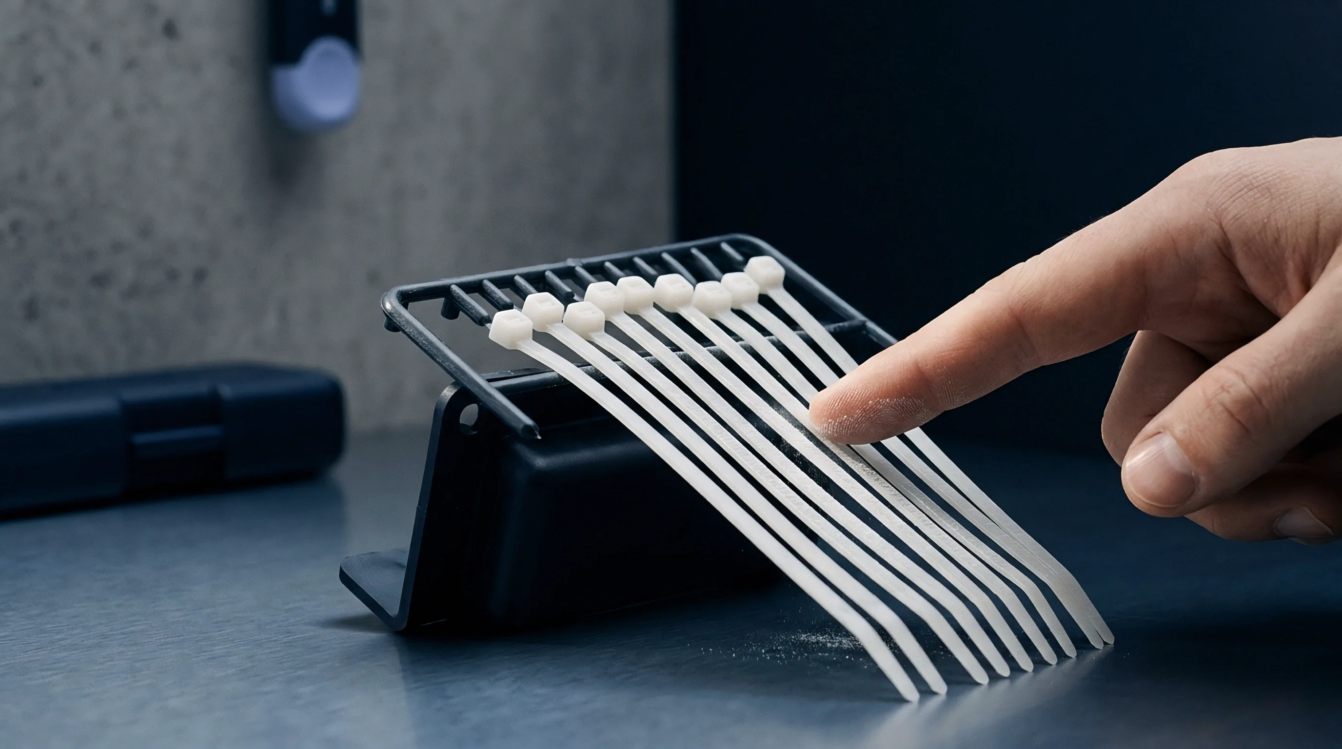
Harness strain relief requires specific mechanical anchor blocks at all tool exits. Tie-wraps are unacceptable. Split-jaw aluminium clamp blocks equipped with Santoprene grommets absorb machine acceleration shocks without pinching internal wire cores.

Signal Crosstalk in Dense Bundles
Packing high-voltage heater wiring alongside micro-volt and pico-coulomb sensor lines in the same conduit creates extreme inductive and capacitive crosstalk. A 230-volt hot runner heater pulling 15 amperes generates magnetic fields that couple noise into adjacent low-impedance cables. The problem intensifies during soft-start modes when hot runner controllers pulse heaters with phase-cut current profiles, inducing high dI/dt transitions.
Separation rules dictate absolute physical segregation. Tool drawings must show distinct physical raceways on opposite sides of the mould base: heater and power connections exit to the non-operator side, while instrumentation signals exit to the operator side. In tight multi-plate tools where crossover is mechanically unavoidable, channels must intersect at 90-degree right angles.
Running instrumentation lines parallel to heater circuits without an intervening steel rib compromises the integrity of every sensor trace.
A minimum isolation distance of fifty millimetres of solid tool steel prevents capacitive coupling between hot runner power feeds and piezoelectric sensor lines.
Shielded twisted-pair layouts attenuate capacitive coupling by presenting balanced surface areas to external noise sources. Noise spikes couple equally into both the positive and negative conductors, enabling the downstream differential amplifier to cancel the induced voltage via common-mode rejection. Standard coaxial arrangements lack this symmetry, leaving single-ended charge amplifiers exposed to noise spikes during high-tonnage clamp engagement.
Contractual terms should dictate clear penalties for poor harness segregation during tool build. The SPI mold specification guidelines state that all instrument wiring must remain isolated from power channels throughout the entire tool structure, and failure to meet this baseline justifies immediate shipment refusal.
Proof
How Does Loop Testing Verify Cavity Signal Integrity?
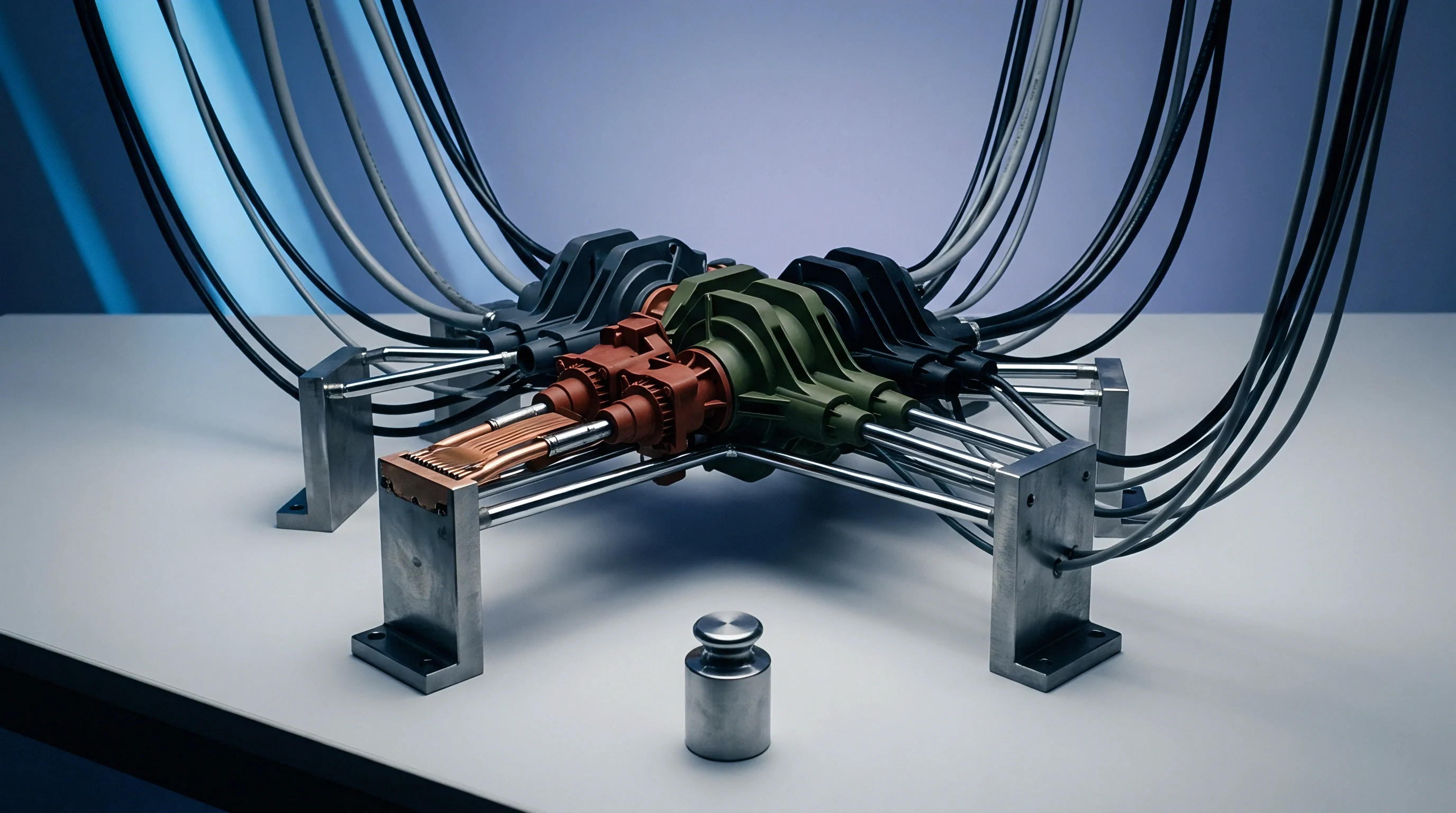
Verification protocol for a wired multi-cavity mould requires strict bench-top testing before the tool is loaded into a press. Waiting for machine trial T1 to identify a crushed cable or crossed pinout wastes expensive press time and risks crushing delicate sensors. Systematic loop verification validates the electrical health of the entire channel stack from the sensor tip to the master output connector.
Technicians employ a high-voltage insulation tester to confirm insulation resistance on all piezoelectric circuits. Applying 100 volts DC between the central conductor and the outer braid must return a reading greater than 10 to the 13th power ohms. If insulation resistance drops below this threshold, contamination inside the cable or a pinhole in the dielectric is present.
Thermocouple circuits undergo loop resistance checks using a precision four-wire Kelvin milliohmmeter to catch pinched wires, poor crimps, or swapped polarities before the mould closes.
The verification sequence follows a strict procedural order:
- Connect the high-resistance meter to individual cavity pins at the main tool interface connector.
- Record the static insulation resistance across all channels in the tooling validation file.
- Apply a calibrated mechanical pre-load of 20 Newtons to each sensor pin face using a deadweight tester to confirm mechanical continuity and charge generation.
- Measure decay rate of the generated charge packet to ensure total line capacitance matches nominal cable specifications within a five percent tolerance window.
- Subject the tool to pre-heating up to 100 degrees Celsius via an external oil or electric cart to verify that thermal expansion does not create intermittent short circuits against plate walls.
Documenting these numbers creates a baseline for the mold qualification dossier. If a tool delivers clean signals on the bench but generates unreadable drift in the press, the root cause lies in external grounding or RF emissions rather than internal tool mechanics.
Cavity Pressure Waveform Analysis
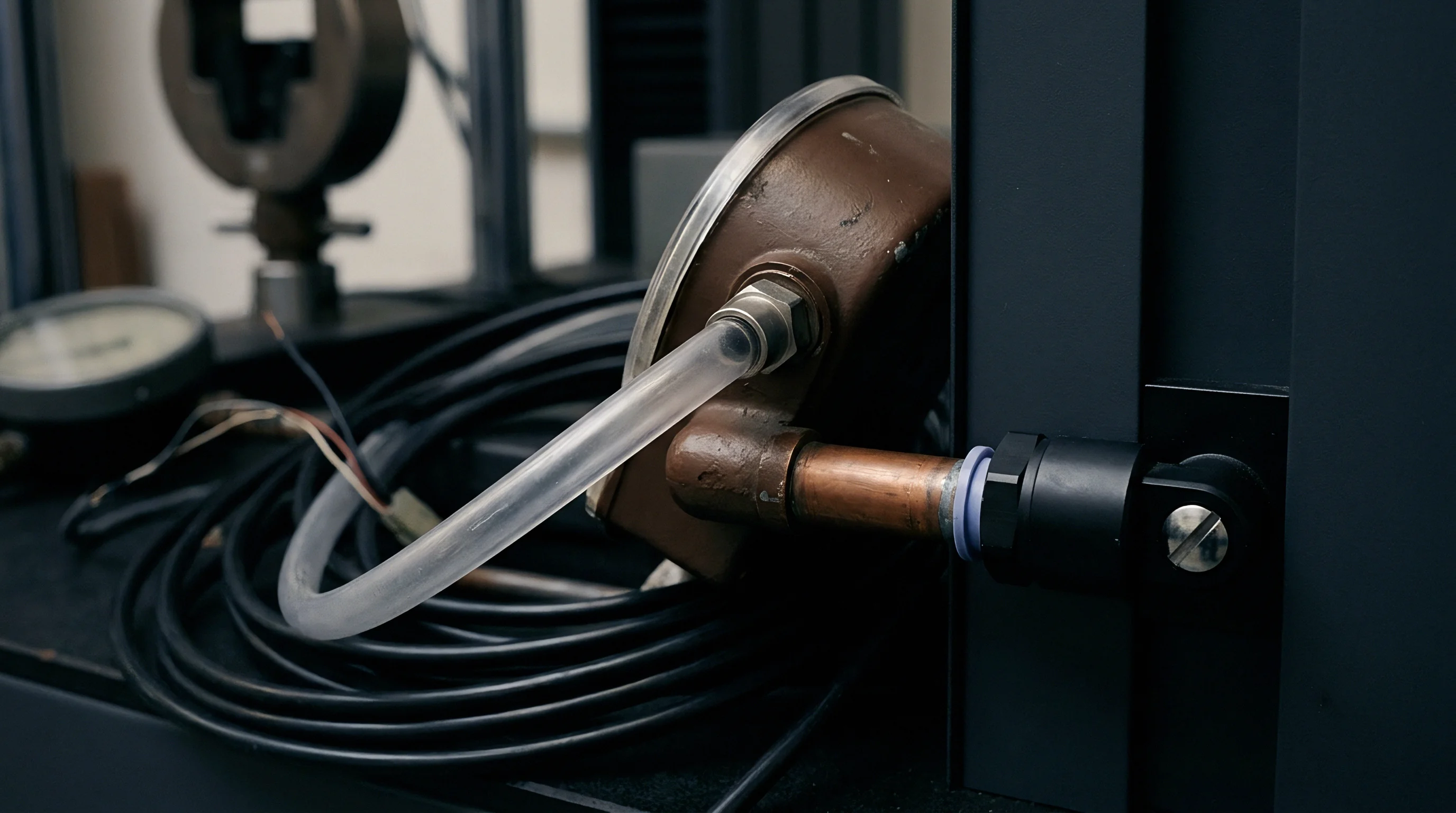
The real-time cavity pressure waveform is an absolute diagnostic indicator of transducer and harness condition. During injection, the sensor registers the melt front hitting the sensor face, the dynamic filling slope, the peak cavity pressure, the hold phase switchover, and the cooling pressure decay curve. Distortions in these phases indicate specific electrical or mechanical harness failures.
A clipped peak indicates that a sensor is mechanically bottoming out against its pocket, or that the charge amplifier input range is improperly ranged for the transducer sensitivity. A negative reading prior to melt arrival reveals excessive mechanical pre-load or deflection of the cavity plate pinching the transducer body. Slow baseline decay indicates insulation breakdown, which bleeds charge to ground during the pack and hold phase.
Noise spikes synchronized with the machine injection forward signal isolate induction pickup from worn servo valve cables.
Analyzing channel-to-channel variations across a 16-cavity tool reveals systemic wiring balance. When identical cavities deliver mismatched pressure curves under balanced melt delivery, the electrical harness is loading the circuits unevenly. Unequal cable lengths produce variation in overall circuit capacitance, subtly shifting the time constant of the charge-amplifier integration loop.
High-cavitation tooling requires matched-length internal coaxial leads to preserve uniform frequency response across all impressions.
The supplier stated that electrical noise during the trials came from machine plant grounding rather than internal harness routing errors.


Margin

Cost Structures of Tool Instrument Architectures
Designing and installing an industrial multi-cavity instrumentation harness carries significant cost. Tool buyers must balance the expense of high-density interconnects, ceramic terminal assemblies, and shielded low-noise cabling against the risk of unmonitored scrap runs. Sourcing choices scale sharply with cavitation count, moving from basic discrete wiring to complex multi-drop junction architectures.
Tooling quotes separate hardware acquisition from precision machining labor. Milling sensor raceways, drilling compound-angle wiring conduits, fitting junction box pockets, and bench-testing terminations adds between 12 and 18 percent to the total machining labor budget of a precision B-plate. For a 32-cavity tool, instrumentation integration adds between 15,000 and 35,000 USD to the initial tooling invoice.
Neglecting this investment leaves the molder blind to intra-cavity filling variations.
| Tool Cavitation Level | Hardware And Component Outlay | Toolroom Machining And Integration | Wiring Redundancy Factor | Annual Preventive Upkeep Cost |
|---|---|---|---|---|
| 8 Cavities | 4,500 USD | 3,200 USD | Single Line Run | 800 USD |
| 16 Cavities | 9,800 USD | 6,500 USD | Spare Pinouts | 1,400 USD |
| 32 Cavities | 21,000 USD | 14,000 USD | 10 Percent Wire Spares | 2,800 USD |
| 64 Cavities | 48,000 USD | 26,000 USD | Dedicated Spare Channels | 5,500 USD |
The financial justification for multi-cavity instrumentation rests entirely on cycle-by-cycle scrap reduction. In high-volume automotive connector or medical component manufacturing, an automated bad-part reject gate driven by cavity pressure limits eliminates entire bin sorts. Detecting a partial short shot or flash event within 15 milliseconds of screw bottoming protects downstream automated assembly cells from jamming.
The cost of a jammed robotic assembly line rapidly outstrips the capital spent on ruggedized tool cabling.

Maintenance Economics and Downtime Risk
Tool downtime remains the primary financial risk over the life of a multi-cavity injection mold. An unarmored signal harness that pinches during an off-shift mold jam halts the entire press cell. Repairing a severed internal wire requires pulling the mold from the platen, cooling it down, stripping the ejector assembly, and re-stringing the transducer line.
This failure costs 8 to 24 hours of lost machine output, exceeding 10,000 USD in unrecoverable press time alone.
Designing modular harness segments mitigates catastrophic downtime. A two-piece harness utilizing intermediate sub-plate disconnects isolates maintenance zones. If a pin breaks in cavity 14, the technician replaces an inexpensive 300-millimetre transducer pigtail without disturbing the main bundle routed through the tool base.
Incorporating 10 percent spare channels into main multi-conductor trunk lines allows instant re-pinning at the external junction box if a primary lead fails in production.
Preventive maintenance programs must include annual deep-cleaning and drying cycles for all junction boxes. Condensation and oil residue accumulate in the bottom of enclosures over thousands of hours of operation. If terminal insulation degrades slowly over six months, scrap rates rise almost imperceptibly as the press control window shifts to compensate for drifting sensor inputs.
The true financial return of disciplined junction isolation architecture is absolute process window stability over millions of cycles.
How toolroom technicians verify that internal cable insulation resistance matches new-build specifications after exposure to five hundred thousand cycles remains an open question in most plant environments.