Mineral Insulated Cable Routing Strategies for High Temperature Mould Telemetry
Recessed MI cable routing with thermal expansion loops prevents wire pinch, shields noise, and eliminates press downtime in high-temperature moulds.
Conduit
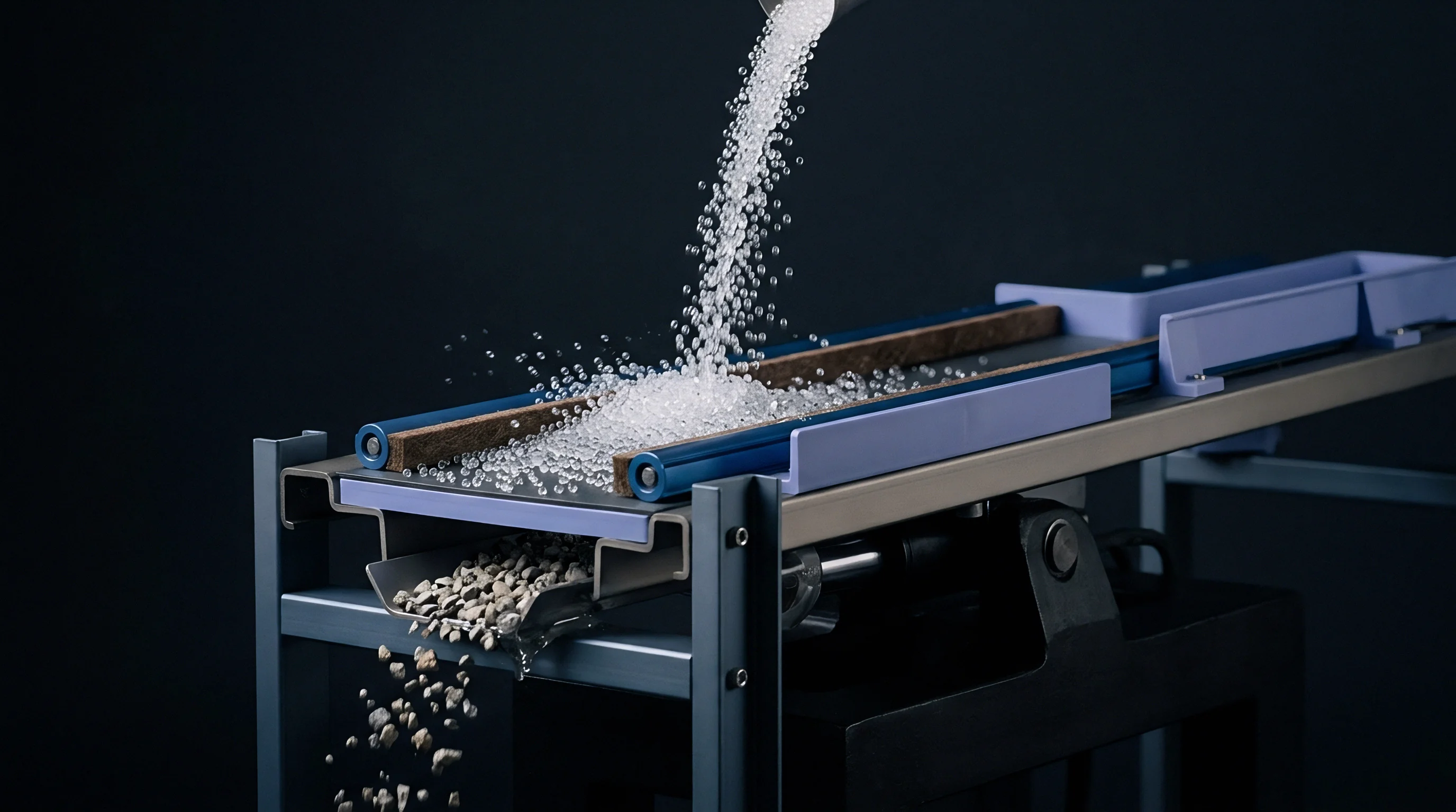
High-temperature injection tools and liquid silicone rubber moulds need continuous telemetry from deep within the steel matrix to control gate seals and track thermal gradients. Mineral insulated cable offers a rugged medium for these signals, wrapping copper, thermocouple alloy, or fiber core lines in compressed magnesium oxide powder inside a malleable metal sheath. Routing these stiff cables through tool plates requires machined channels that protect signal continuity without allowing the sheath to pinch during assembly.
When the press hits full clamping tonnage, steel plates deform and narrow those channels immediately, which crushes sheaths and short-circuits conductors if clearances were miscalculated.
Milled channels need to hold a consistent depth from end to end. Milling a transition corner without a radius leaves a stress concentration point that will shear the outer sheath during thermal cycling. Toolmakers cut these paths with ball-end carbide mills, sizing channel depth slightly larger than the cable diameter so backing plates do not crush the line against manifold assemblies.
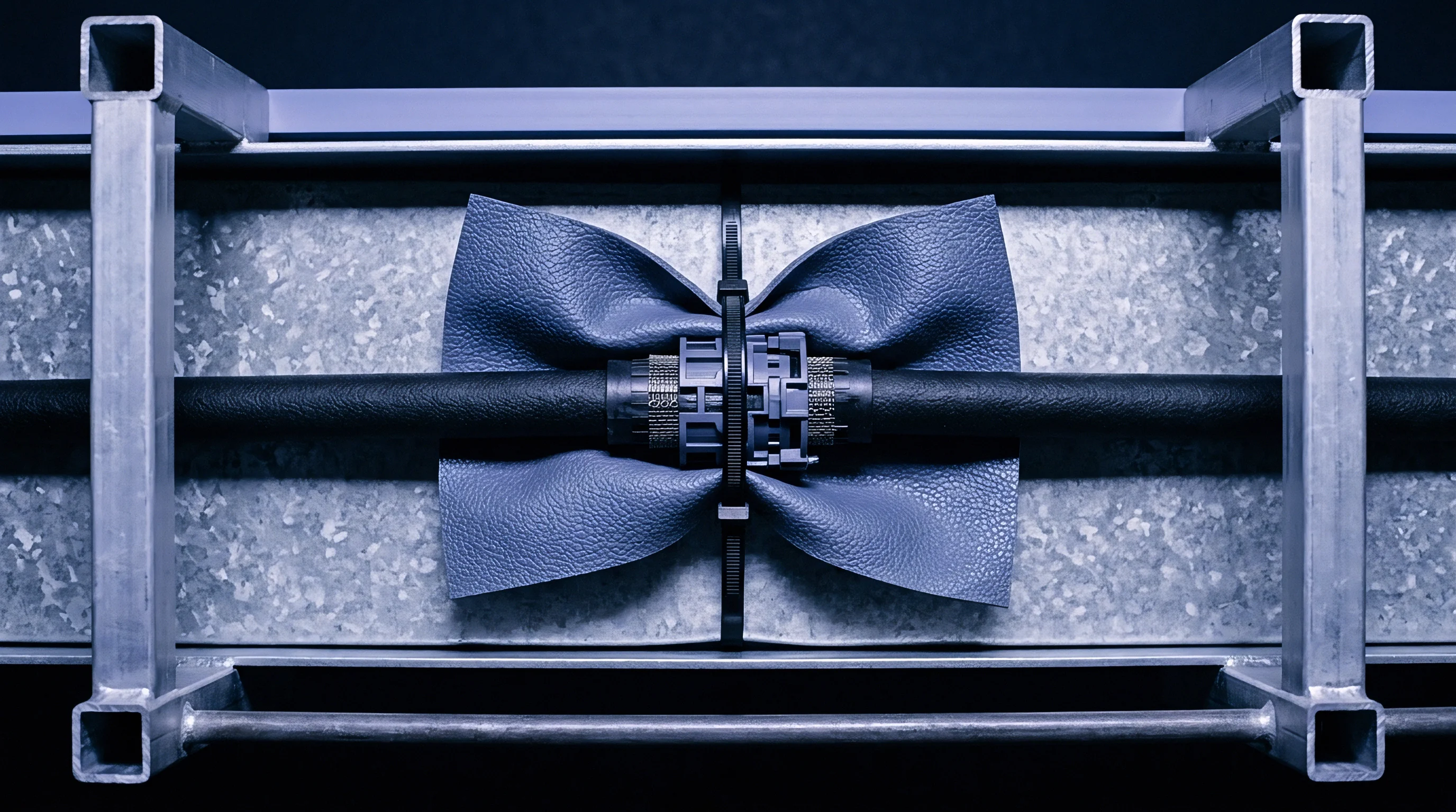
Clamping straps along the run hold the cable steady against high-frequency vibration from hydraulic ejectors and press clamping cycles.
| Cable Outer Diameter | Sheath Alloy | Minimum Bend Radius | Milled Channel Width | Milled Channel Depth | Maximum Strap Pitch |
|---|---|---|---|---|---|
| 0.5 mm | Inconel 600 | 1.5 mm | 0.7 mm | 0.8 mm | 50 mm |
| 1.0 mm | 316L Stainless | 3.0 mm | 1.3 mm | 1.4 mm | 75 mm |
| 1.5 mm | Inconel 600 | 4.5 mm | 1.9 mm | 2.0 mm | 100 mm |
| 2.0 mm | 316L Stainless | 6.0 mm | 2.5 mm | 2.6 mm | 125 mm |
| 3.0 mm | Inconel 600 | 9.0 mm | 3.6 mm | 3.8 mm | 150 mm |
Sharp bends break core wires or thin the magnesium oxide dielectric layer, causing internal arc-overs under ambient electromagnetic interference. Bending mineral insulated cable past its cold-work limit creates micro-cracks in the sheath that draw in hydraulic fluid or vaporized plasticizers. Any turn radius must respect the minimum multiples of cable diameter required by the sheath metallurgy.
A corner radius cut tighter than three times the sheath diameter induces micro-fractures in the metallic sheath during installation.
Cable paths through high-temperature moulds cross parting lines, hot runner manifolds, and core slides, exposing lines to mechanical shear and crushing hazards.
- Sheath pinching occurs when backing plates bolt down directly onto cable runs that lack dedicated clearance channels.
- Work hardening breakdown takes place when repeated manual bending during tool maintenance cracks the outer metal sheath.
- Thermal fatigue fracture stems from uncompensated localized thermal expansion between the steel plate and the cable sheath.
- Dielectric displacement happens when sharp bends compress the internal magnesium oxide powder, letting conductor wires drift toward the outer wall.
Miscalculating channel depth forces the cable to take the full clamping load of the hydraulic press, crushing sheaths and bringing on ground faults or complete signal loss during the first production run.

Expansion
Tool steel and mineral insulated cable sheaths expand at noticeably different rates. Tool steels such as AISI H13 expand at roughly 12.8 micrometers per meter per degree Celsius, while an Inconel 600 sheath expands at 14.2 micrometers per meter per degree Celsius. Across a hot runner plate running at 350 degrees Celsius, that difference generates significant axial force along the cable.
Straight runs without strain relief build up this strain until the cable buckles, shears its sheath, or pops free at connector boundaries.

Designing Expansion Relief Pockets
Machining expansion loops right into the tool plates absorbs differential growth before it stresses terminal connections. The loop is simply an enlarged pocket in the steel where the cable forms a broad omega bend or S-curve. As temperatures rise, the cable flexes inside the pocket instead of pushing hard against rigid termination blocks.
Sizing the pocket with enough depth and width lets the cable float laterally without hitting the pocket walls during heat-up.
| Material Component | Expansion Coefficient | Total Growth at 350°C | Differential Growth | Required Loop Clearance |
|---|---|---|---|---|
| AISI H13 Tool Steel | 12.8 µm/m·°C | 4.16 mm | Baseline | Not Applicable |
| AISI P20 Tool Steel | 12.0 µm/m·°C | 3.90 mm | 0.26 mm short | 1.5 mm |
| 316L Stainless Steel Sheath | 16.0 µm/m·°C | 5.20 mm | 1.04 mm excess | 3.5 mm |
| Inconel 600 Sheath | 14.2 µm/m·°C | 4.61 mm | 0.45 mm excess | 2.0 mm |
Plates moving across guided ejector systems need flexible bridge zones. Routing rigid cable straight across a plate interface causes it to snap as the mold actuates. Transition sleeves or spring-loaded strain relief boots support the cable across open gaps, preserving alignment while keeping bending stresses well within safe limits.
At an operating temperature of 350 degrees Celsius, an Inconel sheath expands nearly half a millimeter more per meter than the surrounding H13 steel cavity plate.
Managing thermal movement requires careful channel preparation at every hot runner boundary.
- Calculate differential displacement using maximum mold operational temperature and baseline assembly temperature.
- Verify expansion loop geometry to ensure lateral flexing stays well within the elastic strain limit of the sheath metal.
- Position anchor blocks at designated neutral points to direct thermal elongation along the milled channel.
- Clear all debris from expansion pockets before mold assembly so foreign material cannot lock the floating loop in place.
Tight bends near termination blocks concentrate thermal stress directly on delicate seal points.


Sealing
Magnesium oxide insulation inside mineral insulated cables is extremely hygroscopic. Exposed cable ends absorb atmospheric moisture within minutes, dropping insulation resistance from gigaohms down to zero. That moisture causes rapid signal leakage in high-impedance sensors and catastrophic shorts in power-bearing telemetry.
Sealing terminations against mold humidity, cooling water leaks, and vaporized processing lubricants is essential.

How Does Moisture Degradation Alter Magnesium Oxide Resistance?
Water entering the porous magnesium oxide creates a conductive electrolytic path between internal conductors and the outer sheath. Testing insulation resistance with a 500-volt direct current megohmmeter shows immediately if moisture has entered. Readings under 100 megaohms indicate contamination that requires a thermal bake-out before finalizing epoxy or ceramic potting boots.
Hermetic potted seals use high-temperature fluoropolymer sleeves, ceramic potting compounds, or glass-to-metal seals at termination headers. Epoxy compounds work reliably up to 200 degrees Celsius, whereas ceramic formulations handle zones above 400 degrees Celsius. Placing transition joints in cooler mold backing plates isolates lower-temperature epoxies from cavity wall heat.
ISO 20753 telemetry integration standards dictate a minimum insulation resistance of 1000 megaohms at 500 volts direct current prior to permanent potted termination.
Field termination procedures require precise steps to restore electrical integrity before final tool closure.
- Strip the outer metallic sheath back by 15 millimeters using a micro-ring cutter without nicking internal conductors.
- Remove exposed magnesium oxide powder back to clean metal using a soft bristle precision pick.
- Apply a high-temperature heat gun along the final 100 millimeters of sheath, working outward toward the exposed end to drive out trapped moisture.
- Measure insulation resistance immediately with a megohmmeter to confirm a reading exceeding 1000 megaohms.
- Fill the transition sleeve with high-temperature epoxy or ceramic compound, ensuring zero air void entrapment.
- Crimp the transition sleeve onto the outer sheath and slide a heat-shrinkable fluoropolymer boot over the joint.
Factory-sealed mineral insulated cables remain impervious to moisture during storage, yet unsealed ends exposed on a humid workshop floor degrade beyond recovery within hours.
Shielding
Injection presses generate high levels of electromagnetic noise from heating bands, servo motors, and hydraulic solenoid valves. High-temperature telemetry signals ~ especially microvolt thermocouple outputs and charge signals from piezoelectric pressure transducers ~ corrupt easily if noise couples into the signal line. The metallic sheath of a mineral insulated cable acts as an effective coaxial shield, provided grounding prevents ground loop currents.
Single-point grounding prevents circulating currents along the cable sheath. Grounding the sheath at both the tool plate and the data acquisition cabinet forms a loop between different ground potentials. High noise currents flowing through the sheath then induce noise voltages in internal signal wires via capacitive and inductive coupling.
Terminating the sheath ground only at the data acquisition panel and isolating the sensor body at the mould plate keeps machine noise out of the signal path.
Piezoelectric pressure sensors rely on high-impedance charge amplifiers that are sensitive to triboelectric noise. If a cable vibrates inside a loose routing channel, friction between the sheath, magnesium oxide powder, and core wires produces static charge spikes that distort pressure traces. Clamping the cable firmly at short intervals stops physical movement and eliminates this noise.
Continuous sheath contact along milled channels reduces electromagnetic noise pickup by forty decibels compared to floating wire runs.
Differential signal processing with twisted double-core mineral insulated cables offers far better noise rejection than single-core coaxial lines. Because common-mode noise affects both conductors equally, differential amplifiers at the acquisition module subtract it out, protecting microvolt thermocouple signals during aggressive processing cycles.
When high-frequency induction heating coils operate right next to shielded mineral insulated cables inside smart hot-runner plates, localized magnetic coupling remains a potential source of signal corruption.

Amortization
Integrating mineral insulated cable routing into tool design increases upfront machining costs, but it drops long-term maintenance overhead substantially. Loose wiring across open plate surfaces frequently snagged, burned, or crushed during tool setup, causing emergency press downtime and lost production shifts. Machining internal routing channels protects telemetry assets across millions of molding cycles, turning telemetry line items from ongoing repairs into long-term capital tooling.
Cutting precise channels, expansion loops, and junction pockets increases machine hours during toolmaking. Ball-end carbide milling, tap drilling for strap points, and wire-EDM transition ports add roughly two to four percent to initial plate fabrication budgets. But surface wiring fails frequently, causing unplanned downtime that quickly wipes out any initial savings.
| Cost Parameter | Surface Wire Installation | Recessed MI Cable Routing | Variance Impact |
|---|---|---|---|
| Initial Tool Machining Cost | €500 | €2,800 | €2,300 higher upfront |
| Cable Assembly Material Cost | €150 | €850 | €700 higher material |
| Unscheduled Maintenance Hours | 48 hours | 2 hours | 46 hours saved |
| Cable Replacement Frequency | 8 replacements | 0 replacements | 8 fewer interventions |
| Total Downtime Financial Loss | €14,400 | €600 | €13,800 total savings |
Procurement specifications need to detail telemetry routing before steel is cut to avoid costly mold retrofits. Defining channel requirements in the initial tooling request ensures toolmakers build proper clearances into 3D CAD models, preventing clashes with cooling lines or ejector pin holes.
- 3D CAD clearance validation requires full collision modeling between wire channels, water lines, and ejector pins before machining blocks.
- Spare routing paths require cutting secondary channels so sensors can be re-wired quickly without removing plates from the press frame.
- Standardized strap geometry ensures toolmakers use uniform clamping hardware across all mold plates, simplifying spare parts inventory.
- Terminal box protection requires embedding primary transition blocks into recessed pockets fitted with steel cover plates.
Recessed telemetry channels protect expensive sensor wiring and ensure continuous monitoring throughout the production life of high-temperature injection tooling.