In-Cavity Pressure Sensor Integration for Closed-Loop Volumetric Decoupled Process Control Verification
In-cavity pressure sensors control volumetric fill by triggering V/P switchover from actual cavity pressure, eliminating batch viscosity shift effects.
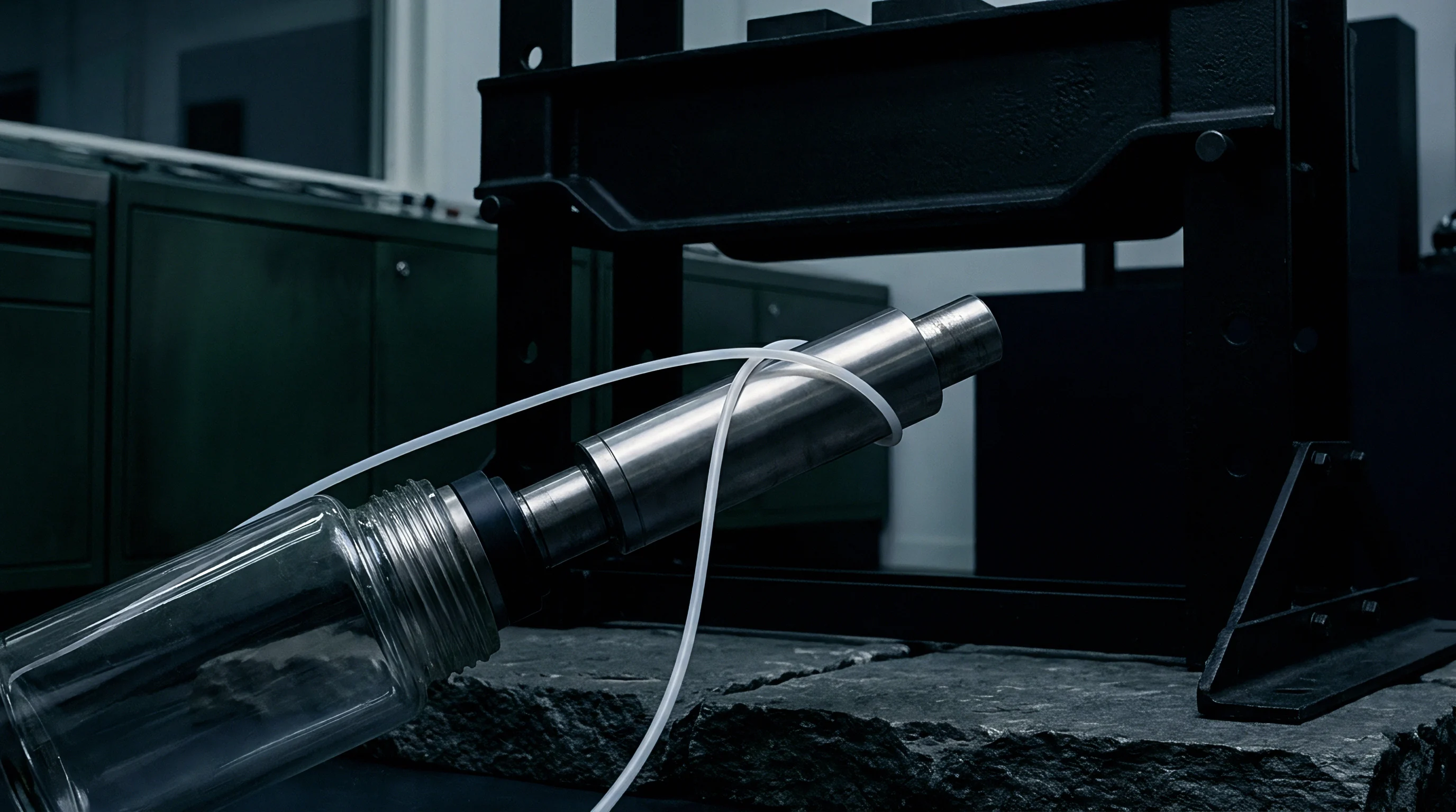

Trace
In-cavity sensing changes how an injection moulding machine tracks the melt front during high-speed filling. Traditional setups switch from velocity-controlled filling to pack and hold based on screw position, line hydraulic pressure, or timers. These machine-side parameters miss the melt viscosity shifts caused by resin lot variance, changing regrind ratios, moisture swings, or thermal shear along the barrel.
Placing a sensor inside the cavity gives a direct, real-time readout of the polymer melt front as it moves through the tool.
Piezoelectric crystals produce an electric charge proportional to applied mechanical stress. When melt strikes the sensor diaphragm or acts against a force transmission pin, the quartz element generates a signal measured in picocoulombs per bar. Because this crystal assembly is exceptionally stiff, it captures transient pressure spikes without measurable mechanical deflection.
Strain gauge transducers rely instead on a metallic or semiconductor foil element bonded to a flexing membrane, producing a continuous voltage as resistance shifts under load. However, changing melt temperatures also shift strain gauge resistance, requiring active bridge compensation inside the sensor housing.
Peak cavity pressure variations exceeding 15 bar in semi-crystalline polyamide formulations alter linear shrinkage by 0.12 percent across a 100 mm nominal dimension.

Piezoelectric versus Piezoresistive Transducer Dynamics
Sensor chemistry dictates signal response speed during high-speed cycles. In thin-wall mouldings with fill times under 0.3 seconds, pressure rise rates can exceed 5000 bar per second. Piezoelectric quartz sensors offer natural frequencies above 100 kHz, fast enough to prevent signal ringing and phase lag as volumetric fill terminates.
Piezoresistive sensors, which use internal silicon diaphragms, resonate much lower ~ typically between 15 kHz and 30 kHz. Rapid melt transients trigger electronic ringing in these piezoresistive units, risking false switchover triggers.
A charge amplifier converts the high-impedance quartz signal into a 0 to 10 V direct current analogue output for machine closed-loop processing. Over extended cycles, however, charge bleeds away across cable insulation and amplifier inputs. Thick-walled parts needing hold times above 60 seconds therefore suffer from signal drift when running on piezoelectric hardware.
Strain gauge sensors maintain a stable direct current voltage without charge decay during long packing phases. Choosing between them depends on the cycle duration and the initial pressure rise rate.
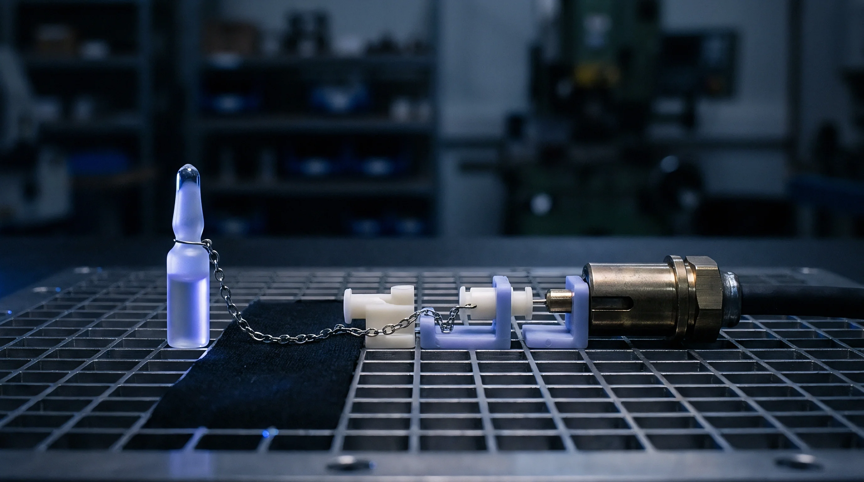
Signal Acquisition Rates for High-Velocity Injection
Executing switchovers within sub-millisecond windows requires fast sampling at the controller card. At a 1 kHz acquisition rate, the machine reads cavity pressure only once every 1.0 millisecond. If the screw moves at 300 mm per second, it travels 0.3 mm between readings ~ enough volumetric variation to alter part weight and optical clarity.
Decoupled process controllers avoid this by using dedicated analog-to-digital cards sampling at minimum rates of 10 kHz per channel.
Operating at those speeds demands shielded wiring and single-point grounding to keep out servo-drive electrical noise. Microvolt-level charge signals routed alongside motor leads pick up 50 Hz or 60 Hz hum that obscures the true cavity pressure inflection point. Cable runs must be isolated within grounded steel conduit, and connectors require gold-plated pins rated for mould temperatures up to 200 °C to prevent leakage paths across the insulation.
Machine-side screw position control provides predictable repeatability for some semi-crystalline resins, but it misses the melt viscosity shifts that occur between raw polymer lots.


Transfer
Decoupled moulding isolates part formation into distinct mechanical phases. Decoupled I separates filling from packing through screw position switchover. Decoupled II fills 95 to 98 percent of the cavity volume under fast velocity control, applies a hydraulic hold pressure to finish filling, and packs the part until the gate freezes.
Decoupled III runs velocity control right up to 99 percent of cavity volume, transferring directly to cavity pressure control to pack and hold the melt without influence from machine hydraulic dynamics.
Switching on cavity pressure removes machine mechanical compliance from the equation. Cushion variations, non-return valve leakage, and hydraulic oil compressibility alter delivered shot volume even when the ram stops at the identical forward position. Transferring from fill to pack at a fixed cavity pressure threshold guarantees the tool receives the same polymer mass every cycle regardless of shifts in melt viscosity.

Volumetric Decoupled Process Control Architecture
A sensor near the gate tracks the feed system pressure drop and early cavity fill, providing the feedback needed for dynamic hydraulic profiling to counter runner shear thinning. Placing the sensor near the end of fill marks the exact arrival of the melt at the cavity boundary. This end-of-fill signal provides the most reliable trigger for V/P switchover, preventing flash while ensuring thin-wall details fill out completely.
The difference between stroke-position switchover and cavity pressure transfer is evident in an 8-cavity tool moulding polybutylene terephthalate (PBT) automotive connector housings with a 0.8 mm nominal wall thickness. Melt temperature runs at 260 °C, mould temperature is held at 80 °C, and injection velocity is set to 180 mm/s. Polymer lot variations introduce a ±8 percent viscosity shift across production runs.
With stroke switchover set at 12.5 mm remaining screw position, an 8 percent viscosity drop reduces flow resistance. The melt surges ahead and packs the cavity prematurely during the velocity phase, driving peak cavity pressure from 450 bar up to 580 bar. Flash forms across the parting line, producing 3.4 percent scrap across a 50,000-unit production lot.
Moving switchover to an end-of-fill sensor set at a 320 bar threshold forces the controller to pack the moment melt reaches that location. Peak cavity pressure holds at 455 bar ±4 bar across the entire viscosity window, and dimensional variance on the 0.8 mm terminal pin alignment slots tightens from ±0.045 mm down to ±0.012 mm, meeting ISO 2768-m standards.

Switchover Trigger Thresholds in Multi-Cavity Moulds
Finding the correct switchover threshold requires analyzing pressure curves across short-shot progression runs. Setting the transfer pressure too low causes the controller to shift to packing mode before the flow front reaches the edges of the tool, leaving weld lines weak and causing short shots or hesitation marks. Setting it too high lets the screw pack the cavity at full injection velocity, inducing moulded-in stress, gate-area sink, and parting-line flash.
Multi-cavity validation requires checking peak pressure balance across every impression. Gate wear, thermal imbalances in the runner, and local viscosity variations create uneven filling. Multi-cavity systems monitor these conditions by aggregating signals through peak detection algorithms or averaging circuits.
Advanced controllers operate individual valve gate needles directly from separate cavity pressure sensors, closing off packed cavities while the rest finish filling.
| Process Control Strategy | V/P Transfer Trigger Source | Volumetric Filling Repeatability | Sensitivity to Melt Viscosity Shift | Achievable Part Weight Tolerance |
|---|---|---|---|---|
| Decoupled I | Machine Screw Position | ±1.2 % Volume | High (Direct transfer drift) | ±0.85 % |
| Decoupled II | Hydraulic / Cavity Pressure Hybrid | ±0.4 % Volume | Moderate (Dampened by pack speed) | ±0.32 % |
| Decoupled III | End-of-Fill Cavity Pressure Sensor | ±0.05 % Volume | Low (Real-time melt compensation) | ±0.08 % |
| Closed-Loop Decoupled III | Real-Time Cavity Pressure Curve Feedback | ±0.02 % Volume | Negligible (Active profile correction) | ±0.04 % |
Setting the V/P changeover threshold on hydraulic pressure rather than cavity melt pressure allows viscosity shifts to translate directly into short shots or flash, invalidating the statistical capability of tight-tolerance sealing faces.


Pin
Mounting configurations dictate sensor reliability, signal fidelity, and mould maintenance schedules. Direct flush mounting puts the transducer diaphragm directly against the polymer melt in the cavity wall, reading real-time surface pressure and rapid temperature changes without mechanical loss. However, if the diametral clearance between the sensor body and cavity bore exceeds 0.005 mm, melt can flash into the gap.
Contact with glass-filled polymers also accelerates diaphragm abrasion, requiring titanium nitride or diamond-like carbon surface treatments.
Indirect mounting places the transducer behind a force transmission pin, typically an ejector or dummy load pin. Melt pressure drives the pin face, transmitting axial force down the shank to the sensor button in the ejector retainer plate. This layout protects sensitive electronics from chemical attack and hot cavity surfaces.
However, pin bore friction and clearance alter the delivered force, requiring empirical calibration correction factors.

Direct Mount versus Indirect Sensor Integration
Flush-mounted sensors demand tight sinker EDM tolerances in the cavity block. The diaphragm recess must sit between zero and plus 0.010 mm relative to the surrounding steel: a recessed mount leaves a raised plastic witness mark, while a protruding mount indents the part and obstructs ejection. Running high-temperature engineering resins like PEEK or PEI also requires thermal isolation sleeves or dedicated cooling lines around direct-mount sensor bodies.

Force Transmission Mechanics and Mechanical Clearance
Indirect force measurement depends entirely on the mechanical interface between the transmission pin and sensor face. The pin must stroke cleanly without axial binding or cocking in its bore, requiring an H7/g6 clearance fit. Excessive clearance allows melt to creep past the pin tip and create mechanical drag, while insufficient clearance causes thermal binding as the cavity plate expands during production.
Force transfer follows the cross-sectional area of the transmission pin multiplied by cavity pressure. A very small pin limits total transmitted force, compressing signal resolution during low-pressure phases. Conversely, an oversized pin transfers heavy mechanical loads into the ejector retainer plate, risking plate deflection that shows up as baseline distortion during part ejection.

Can Cavity Pressure Traces Predict Volumetric Sink Marks?
Sink marks result from volumetric contraction as polymer transitions from liquid melt to solid. In-cavity pressure curves show the exact decay rate of packing pressure in thick wall sections. Keeping cavity pressure above the volumetric expansion threshold during cooling prevents the skin from pulling away from the tool steel.
If the pressure trace drops to zero bar before the gate freezes, pack pressure has released early, making sink marks over internal ribs inevitable.
- Ejector Pin Binding ~ Friction between the pin shank and plate bore absorbs axial force, depressing the transducer reading below true cavity pressure.
- Diaphragm Flash Creep ~ Melt entering the annular gap around flush sensor heads causes mechanical binding and baseline offset drift.
- Preload Deflection Loss ~ Under-torquing the sensor retaining nut allows the body to shift under peak loads, creating non-linear signal hysteresis.
- Thermal Expansion Offset ~ Cavity plate heating expands tool components, applying unintended baseline mechanical load to indirect button sensors.
Measuring force behind an ejector sleeve requires smooth pin movement across the full thermal expansion range of the mold cavity plate.

Drift
Signal verification ensures sensor output matches physical pressure dynamics in the tool across thousands of cycles. In piezoelectric systems, drift appears as a gradual drop in the zero-pressure baseline voltage. Humidity, contaminated cable contacts, and internal charge amplifier leakage bleed charge away.
This signal decay reduces measured pressure amplitude, leading closed-loop controllers to over-pack the mould if drift compensation algorithms are absent.
Thermal zero shift occurs when temperature gradients across the sensor body alter internal mechanical stress in quartz elements or strain bridges. Unbalanced cooling lines, cold water restarts, and thermal stabilization cycles produce transient baseline offsets. Triggering an electronic auto-zero routine during mould-open dead time resets the baseline, ensuring a true zero-pressure reference before each injection stroke.
ISO 294-4 compliance mandates continuous cavity pressure recording during test specimen moulding to establish accurate processing shrinkage reference data.

Charge Amplifier Decay and Signal Offset Mitigation
Charge amplifiers convert low-level electrical charge into proportional direct-current output voltages. High-end amplifiers achieve input resistances above 10 to the 14th power ohms. Contamination on cable insulation drops that resistance by several orders of magnitude, causing rapid signal decay during long hold phases.
Cleaning connectors with high-purity isopropyl alcohol and fitting fluoropolymer sealing caps during storage preserves insulation resistance.
Digital signal processing cards apply drift-compensation logic to filter electrical noise and thermal zero shifts. The controller records baseline voltage during mould opening when cavity pressure is zero bar, then subtracts that offset from the trace acquired during the next shot. Auto-zero routines must be locked out during active injection, pack, and cooling phases to avoid distorting real curve data.

Thermal Expansion Compensation in Multi-Cavity Tooling
Multi-cavity tools develop thermal gradients across core and cavity plates. Impressions positioned next to hot runner drops run warmer than peripheral cavities bordered by exterior cooling channels. This temperature spread causes unequal expansion along force transmission pins, shifting preload values on indirect sensors.
Fitting calibrated disc springs or Belleville washers behind sensor buttons absorbs these thermal differences and maintains a steady baseline load.
- Warm the mould tool to operational thermal equilibrium at the specified coolant flow rate and temperature.
- Perform a dry-cycle actuator reset to re-establish electronic charge amplifier zero voltage.
- Inject five purge shots to clear residual thermally degraded resin from the machine barrel.
- Record baseline piezoelectric charge output prior to cavity filling under active clamping pressure.
- Verify peak signal alignment with master reference pressure curves across eight consecutive validation cycles.
| Integration Architecture | Sensor Technology | Pressure Response Delay | Maintenance Sensitivity | Signal Offset Drift Risk |
|---|---|---|---|---|
| Direct Flush Mount | Piezoelectric Quartz | < 0.5 ms | High (Diaphragm exposure) | Low (Direct contact zeroing) |
| Indirect Behind Ejector Pin | Piezoelectric Button | 1.5 ms to 3.0 ms | Moderate (Pin clearance cleaning) | Moderate (Pin friction effects) |
| Indirect Behind Load Button | Strain Gauge Bridge | 2.0 ms to 5.0 ms | Low (Protected enclosure) | High (Thermal offset sensitivity) |
| Direct Core Pin Mount | Piezoresistive Silicon | 1.0 ms to 2.0 ms | High (Wire routing vulnerability) | Moderate (Bridge balance decay) |
Auto-zeroing charge amplifiers during cycle dead time can mask progressive baseline drift, yet omitting the reset risks introducing electronic offsets into high-speed closed-loop feedback controllers.


Margin
Closed-loop process verification relies on cavity pressure curves to regulate production quality automatically. Real-time controllers check incoming pressure traces against a master template qualified during initial tool validation. Templates set upper and lower control limits for peak pressure, pressure integral over time, and cooling decay rates.
Parts moulded within this envelope feed directly into automated packaging stations.
Cycles falling outside the envelope trigger automated reject gates, isolating suspect parts before downstream assembly. Viscosity shifts beyond machine compensation limits trip alarms to stop production before scrap piles up. Retaining continuous cavity pressure logs provides full lot traceability, meeting automotive IATF 16949 and medical ISO 13485 quality standards.
Positioning the transducer near the end of fill isolates gate seal timing from post-filling volumetric shrinkage control.

Closed-Loop Controller Integration and Feedback Latency
Closed-loop execution requires minimal communication latency between the pressure amplifier and the machine PLC. Analogue 0 to 10 V leads wire directly into high-speed input cards on the bus, while industrial networks using Real-Time EtherCAT or PROFINET IRT deliver updates with latencies below 250 microseconds. That response speed allows controllers to adjust hydraulic servo-valve spools dynamically during fast injection transients.
Advanced closed-loop systems use adaptive profile matching. When resin viscosity rises, the controller automatically increases injection pressure to keep the cavity curve tracking its target trajectory. If viscosity drops, injection speed throttles back to preserve the correct flow front pace.
Screw motion compensates for raw material variations without operator intervention.

Statistical Capability Verification across Polymer Lots
Tooling qualification requires verifying capability indices (Cp and Cpk) across multiple polymer lots. Standard stroke-controlled injection typically achieves Cpk values between 1.00 and 1.33 on critical features due to batch-to-batch material shifts. Controlling the process via in-cavity pressure lifts capability indices above 1.67, satisfying Six Sigma requirements on critical dimensions.
Commercial payback is clear in high-volume applications. A 16-cavity tool running medical syringe barrels on a 6.5-second cycle produces 7,950 units per hour. Retrofit costs ~ 16 piezoelectric sensors, multi-channel amplifiers, ejector plate pocketing, and software integration ~ total 42,000 USD.
Scrap rates under standard screw-position control average 1.85 percent due to raw material viscosity swings and thermal drift across 24-hour production runs.
Closed-loop cavity pressure control reduces scrap to 0.12 percent by eliminating short shots, flash, and sink. The resulting material recovery equals 138 units per hour, which at 0.04 USD per raw unit cuts direct scrap costs by 5.52 USD per hour. Eliminating manual sampling and part sorting saves an additional 4.20 USD per hour, yielding 9.72 USD per operational hour in total savings.
Over a 6,000-hour production year, net savings reach 58,320 USD, amortising the hardware within 8.6 months of continuous operation.
- Transducer Response Frequency ~ Sensor bandwidth must match injection speeds to resolve steep pressure spikes as thin walls fill out.
- Amplification Charge Drift Rate ~ Multi-cavity tools require low-drift piezoelectric amplifiers that maintain zero-baseline stability across long hold phases.
- Mechanical Preload Tolerance ~ Load button mounting requires calibrated torque control to establish preload without distorting cavity steel.
- Controller Bus Latency ~ Real-time networks demand bus cycle times below 500 microseconds to execute active servo-valve volumetric adjustments.
- Cavity Pressure Profile Overlays ~ Part sign-off packages require superimposed live curves for all cavities across fifty consecutive cycles.
- Volumetric Switchover Delta Logs ~ Quality tracking dossiers must record hydraulic versus cavity pressure transfer timestamps to confirm sensor triggering.
- Transducer Calibration Certificates ~ Tool qualification records require factory calibration sheets tying each sensor serial number to its mould cavity position.
- Process Capability Calculation Summaries ~ Qualification dossiers must report Cpk indices for critical dimensions evaluated during closed-loop runs.
Standard procurement contracts specifying DIN 16742 TG3 tolerances require closed-loop cavity pressure verification data to accompany every production lot sign-off.