Finite Element Stiffness Inversion in Thin Wall Automotive Moulding Verification
Finite element stiffness inversion back-calculates local anisotropic moduli from physical test deflections, eliminating costly tool re-cuts and wall thickening.
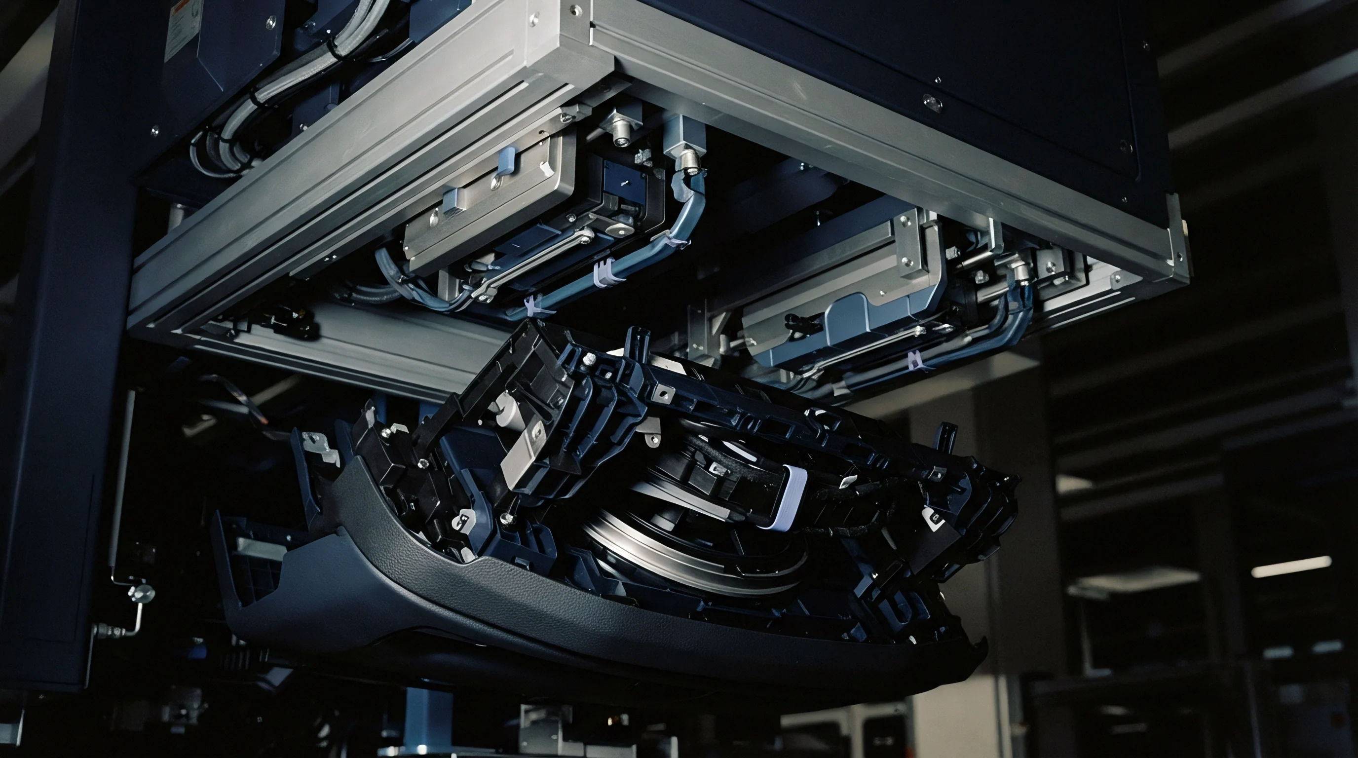

Deflection
Automotive exterior fascias, rocker covers, and instrument panel carriers molded at nominal wall thicknesses between 1.8 mm and 2.5 mm display structural behavior that deviates sharply from isotropic linear elastic simulations. When a hydraulic actuator applies a point load of 150 N to a 2.0 mm polypropylene fascia reinforced with 20 percent talc, measured displacement frequently exceeds the nominal finite element prediction by 30 to 45 percent. The discrepancy does not stem from element formulation flaws in standard shell solvers.
Melt flow length ratios exceeding 150:1 generate severe skin-core morphological gradients across large projected surface areas. As the polymer melt freezes against cooled tool steel, shear stresses align mineral platelets and rubber modifiers parallel to the mold surface, leaving a disorganized, low-modulus core sandwiched between high-modulus skins.
Standard computer-aided engineering dossiers delivered by Tier 1 molders rely on flexural moduli harvested from ISO 527 tensile bars or ISO 178 three-point bend plaques. These test coupons undergo balanced injection under uniform packing conditions without long cross-cavity shear paths. Inside a production injection tool carrying four sequential valve gates, flow fronts converge at varying melt temperatures, creating localized weld lines and variable orientation angles.
Fibers freeze along shear paths. Rib roots act as hinges. When structural engineers test the physically molded bumper assembly in a push-stiffness verification rig, the component registers excessive compliance around the fog lamp pockets and lower grilles.
A bumper fascia predicted to deflect 4.2 mm under a 200 N hand-push force regularly yields 6.8 mm on the physical test track when molders rely on raw tensile plaque data.
Forward simulations that apply a single isotropic Young modulus fail to represent the spatial distribution of mechanical resistance. Finite element stiffness inversion solves this problem by working backward from physical load-displacement fields captured across the physical molding. By capturing actual full-field displacement vectors under controlled proof loads, the numerical method recalculates the localized transverse and longitudinal shell stiffness parameters across individual element partitions.
Thin walls buckle under compression. Secondary cooling locks in stress.
Failure modes emerge across the vehicle assembly line when validation teams bypass this inversion step:
- Peripheral snap unseating occurs when localized lower-than-modeled flange bending stiffness allows retention clips to disengage during automated robotic deck-lid installation.
- High-speed aerodynamic fluttering develops along unsupported lower fascia splitters when pressure fields depress the component past the clearance envelope of the front subframe crossmember.
- Acoustic seal blow-by manifests around door carrier modules under high cabin pressurization cycles because compliant perimeter walls deflect away from closed-cell EPDM weatherstripping gaskets.
When engineering teams fail to invert the physical compliance matrix back into the shell mesh before freezing mold geometry, the assembly encounters chronic dimensional interference in pilot production, triggering expensive tool modifications and line stoppages.

Jig
Physical measurement protocols dictate the fidelity of any mathematical inversion. Setting an injection-molded instrument panel carrier onto a three-point kinematic bench requires strict isolation of rigid-body rotation from genuine shell deformation. The measuring apparatus employs aluminum datum blocks machined to replicate car-body body-in-white attachment points under ISO 2768-m tolerances.
Pneumatic toggle clamps hold the moulding by its primary locating holes while a multi-axis gantry drives a load cell fitted with an elastomeric spherical tip against selected functional zones. High-speed stereoscopic optical cameras monitor three-dimensional digital image correlation speckle patterns sprayed over the component surface.
Displacement fields expose shell soft spots. To invert the stiffness matrix reliably, the physical loading sequence must stay strictly within the linear viscoelastic limit of the thermoplastic. Applying excessive contact pressure drives the material past its proportional limit, corrupting the inverse solver with plastic strain artifacts.
For a typical 30 percent short-glass-fiber reinforced polyamide 66 structural carrier conditioned at 50 percent relative humidity, the linear limit sits below 0.8 percent strain at 23 degrees Celsius. The measurement sequence establishes the empirical baseline through disciplined physical execution:
- Mount the untrimmed molding into the datum nest and engage locating pins without applying secondary clamp force.
- Torque pneumatic retention toggles to 2.5 Nm in the specified cross-diagonal pattern to neutralize mounting distortion.
- Acquire reference stereoscopic images across the full speckle-painted shell geometry to confirm zero-strain baseline conditions.
- Apply an initial seating pre-load of 5 N to settle contact compliance at the actuator interface.
- Advance the ball indenter at a fixed displacement rate of 2.0 mm per minute while logging load-displacement channels at 100 Hz.
- Capture simultaneous full-field digital image correlation strain maps at load increments of 10 N up to the proof threshold.
- Retract the actuator and log residual deformation after a five-minute relaxation interval to ensure elastic recovery.
Clamping tonnage distorts peripheral flanges. Deflection data reveals the error. The resulting displacement cloud provides the ground-truth boundary values for inverse finite element model updating.
If the jig fixture deflects under load, that compliance enters the objective function as false structural flexibility. Tool shops frequently claim that their shop-floor test benches maintain complete structural rigidity, explaining away calibration mismatches by asserting that plastic parts simply conform to whatever fixture supports them during manual measurement.


Mesh
Numerical discretization of thin-wall mouldings presents complex formulation challenges when calibrating local material tensors. Automotive exterior parts feature aspect ratios where thickness spans 2.0 mm while surface lengths extend beyond 1,500 mm. Solid brick elements like eight-node hexahedrals require three to five layers across the thickness to capture bending gradients accurately, creating mesh densities exceeding twenty million degrees of freedom that crush inverse optimization algorithms.
Consequently, structural analysts deploy first-order shear-deformable shell elements based on Reissner-Mindlin kinematics. These elements capture out-of-plane shear flexibility while preserving computational throughput.
How Does Inversion Reconcile Measured Shell Deflections?
Shell solvers discretize the surface into discrete property zones. Rather than treating the component as a monolithic volume, the inverse pipeline partitions the continuous mesh into discrete morphological domains mapped from injection molding simulation flow paths. In each domain, the local constitutive tensor contains independent orthotropic components: longitudinal modulus, transverse modulus, in-plane shear modulus, and Poisson ratios.
The optimization solver minimizes the squared residual between the digital image correlation displacement vectors and the simulated node displacements under identical boundary conditions.
The inverse solver minimizes the global objective scalar by adjusting the constitutive properties of each element cluster through gradient-based Levenberg-Marquardt or adjoint sensitivity methods. Plastics remember how they flowed. Core metal conducts heat slower.
In long-glass-fiber polypropylene mouldings, fiber alignment follows velocity gradients through converging gates, producing an anisotropic ratio where longitudinal modulus reaches 5,800 MPa while transverse modulus hovers near 2,600 MPa. An isotropic assumption of 4,000 MPa underpredicts transverse bending while overestimating torsional stiffness.
Under a 23 degrees Celsius steady-state environment, shell element models calibrated via physical inversion predict final load deflections within 3 percent of track tests, compared to 38 percent error in uncalibrated nominal runs.
Inverting the stiffness of shell elements requires mathematical dampening against experimental noise. Geodetic scientists face identical mathematical instability when inverting satellite gravitational perturbations to map mantle density variations deep within the earth crust. In both domains, ill-conditioned matrices amplify high-frequency measurement errors into wild, unphysical parameter oscillations.

What Governs Parameter Regularization in Ill-Conditioned Compliance Shells?
Tikhonov regularization constrains the inverse optimizer by penalizing steep property gradients between adjacent element clusters. Without this mathematical damping, the solver assigns unrealistically high stiffness to elements directly beneath physical load points while stripping modulus from neighboring elements. The regularized objective function balances deflection error against the smoothness of the spatial stiffness distribution.
The calculation updates element moduli.
| Component Zone | Nominal Wall (mm) | CAD Modulus (MPa) | Inverted Longitudinal (MPa) | Inverted Transverse (MPa) | Displacement Error (mm) |
|---|---|---|---|---|---|
| Upper Grille Brow | 2.2 | 1,850 | 2,120 | 1,340 | +1.85 |
| Fog Lamp Pocket Outer | 1.9 | 1,850 | 1,680 | 1,120 | +2.40 |
| Central Splitter Web | 2.4 | 1,850 | 2,350 | 1,510 | -0.60 |
| Wheel Arch Return Flange | 1.8 | 1,850 | 1,540 | 1,050 | +3.15 |
| Emblem Mounting Boss Base | 2.5 | 1,850 | 1,910 | 1,420 | +0.90 |
| Data acquired under a 120 N static probe load applied at 2.0 mm per minute; displacement error represents nominal FE minus physical DIC measurement. | |||||
When modeling rib-to-skin transitions, shell models introduce artificial stiffness because mid-surfaces intersect without accounting for the local mass accumulation and fillet radii. Inverse methods correct this junction compliance by modifying the rotational stiffness of the connecting element boundaries. Fine meshes resolve spatial gradients reliably only when the physical test data carries sufficient spatial resolution to constrain every free variable.

Penalty
Engineering changes executed after steel hardening impose severe financial and temporal penalties on an automotive program. Discovering inadequate structural stiffness during initial physical pilot runs forces moldmakers to make painful choices. The tool steel cannot stretch.
Increasing nominal wall thickness across an entire fascia requires electrical discharge machining to sink the cavity deeper into hardened P20 or 718H steel blocks, adding raw material mass and extending cycle times. Stiffening through rib additions requires cutting deep, narrow slots into core inserts, creating ejection issues and thermal hot spots that promote cosmetic sink marks on show surfaces.
Consider an operational scenario involving a single-cavity front bumper fascia tool producing 120,000 parts annually over a four-year vehicle platform life cycle. The original design specifies a nominal wall thickness of 2.0 mm molded in talc-filled polypropylene with a quoted cycle time of 42 seconds running on a 2,500-tonne hydraulic injection press. Machine hour rates for this press class sit at 145 dollars per hour.
The tool costs 420,000 dollars to cut, harden, texture, and commission.
When physical verification reveals that the lower valence deflects 7.5 mm under aerodynamic drag force instead of the allowable 4.0 mm, the engineering team evaluates three corrective actions. The first path increases wall thickness from 2.0 mm to 2.4 mm by milling the core steel. Thermal conduction scales with the square of wall thickness.
The cooling time increases by 7.2 seconds, lifting total cycle time to 49.2 seconds. Over the annual volume of 120,000 units, those 7.2 additional seconds consume 240 additional press hours, generating 34,800 dollars in annual machine overhead. Over the four-year program, cycle time loss drains 139,200 dollars.
Furthermore, the 20 percent weight increase adds 0.48 kg of resin per shot. At 1.85 dollars per kilogram, material consumption consumes 106,560 dollars annually, totaling 426,240 dollars across four years. The core re-machining itself costs 28,000 dollars in toolroom labor and trial time.
The second corrective path leaves the nominal wall unchanged and relies on finite element stiffness inversion to identify three discrete zones requiring structural ribbing. By machining six strategic cross-ribs into the core insert, stiffness targets are met without altering nominal cooling dynamics. The toolroom modification costs 14,500 dollars.
Cycle time rises by only 1.0 second due to localized rib root cooling, consuming 4,833 dollars annually in press time. Material mass increases by a negligible 0.04 kg per molding, adding 8,880 dollars in resin over the four-year contract.
DIN 16742 Group 140 tolerance rules mandate that post-tooling wall modifications exceeding 0.2 mm void original dimensional capability agreements, shifting part warpage liability onto the buyer.
The third path implements internal gas-assist channels along the lower perimeter lip. Tooling modifications for gas injection nozzles and nitrogen manifold lines demand 42,000 dollars in upfront capital. The process reduces overall part weight by coring thick perimeter ribs, dropping cycle time by 2.5 seconds compared to the baseline, which generates an annual press time savings of 12,080 dollars.
Nitrogen licensing fees and maintenance add 6,000 dollars annually.
| Correction Strategy | Tool Modification Cost | Cycle Time (s) | Lifetime Machine Cost | Lifetime Resin Cost | Total Financial Impact |
|---|---|---|---|---|---|
| Uniform Wall Increase (+0.4 mm) | $28,000 | 49.2 | +$139,200 | +$426,240 | +$593,440 |
| Inversion-Targeted Ribbing | $14,500 | 43.0 | +$19,332 | +$35,520 | +$69,352 |
| Selective Gas-Assist Coring | $42,000 | 39.5 | -$48,320 | -$17,760 | -$24,080 |
Purchasing agreements governing high-volume automotive injection tools require defined verification gates before steel release. A robust sourcing contract defines how structural stiffness data reconciles with dimensional compliance sign-offs:
- Finite element correlation thresholds define that calculated deflection under specified proof loads must match physical jig readings within 5 percent across all primary locating zones before sign-off.
- Localized thickness caps prohibit toolmakers from increasing nominal wall sections by more than 0.10 mm to solve localized structural compliance failures.
- Cycle time guarantees hold the molder accountable for machine overhead costs if post-trial cooling adjustments exceed the baseline quoted press cycle by more than 3 percent.
- Material property provenance records require test plaques sampled directly from initial production batches to verify orthotropic moduli using ISO 527-2 Type 1A specimens cut along parallel and perpendicular flow vectors.
Under standard automotive supply contracts governed by VDA 6.3 audit protocols, unverified stiffness failures discovered during production trial stages permit the OEM to reject production tooling milestones, freezing commercial payment releases until the Tier 1 molder validates structural compliance at its own expense.

Audit
Quality engineers reviewing injection molding verification dossiers must inspect the numerical methodology as rigorously as coordinate measuring machine reports. Sourcing teams frequently review finite element validation decks that present beautiful stress contours without revealing underlying material cards. When examining supplier reports, the auditor examines the specific constitutive model assigned to thin shell elements.
If a 30 percent glass-filled polypropylene component carries a single isotropic MAT1 linear elastic property deck in Nastran or an isotropic elastoplastic law in Abaqus, the simulation model fails to reflect the physical reality of the pressed part.
The press operator adjusted packing. Shrinkage tracks local molecular orientation. Verification dossiers must contain clear evidence of structural inversion or mapped anisotropic flow properties derived from injection fill simulations like Moldflow or Moldex3D.
The flow simulation predicts fiber orientation tensors across the mid-plane and skin layers. Advanced structural workflows map these tensors directly into structural elements via orientation homogenization models like Mori-Tanaka or Mori-Tanaka-Benveniste schemes. Inverse model updating closes the remaining loop by tuning the mapped field against physical load-displacement test data.
A simulation deck lacking anisotropic flow mapping represents a rough geometric concept rather than a verified manufacturing dossier.
Auditing the physical test records requires inspecting the digital image correlation test setups. The engineer reviews photographic evidence of boundary condition constraints. Clamp fixtures must sit directly on dedicated vehicle datum points without constraining secondary degrees of freedom that artificially stiffen the part.
Load application points must match vehicle load cases: latching efforts, stone impact zones, step loads, and aerodynamic pressure distributions. The audit traces serial numbers on raw resin certification sheets, ensuring that physical tests utilized the exact compound, masterbatch ratio, and regrind proportion specified in the original automotive bill of materials.
Whether automotive engineering practices will eventually transition to fully autonomous, machine-learning-driven inverse identification routines that calibrate shell stiffness in real time directly from in-mold cavity pressure and ultrasonic sensor arrays remains an unresolved debate across Tier 1 tooling networks.