Designing Restrained Fixture Nesting Geometry and Calibrated Toggle Clamp Plungers
Calibrated toggle clamp plungers prevent unreinforced polymer deflection, ensuring restrained fixture nesting matches nominal CAD assembly datums.
Contact
Coordinate measuring machines record false deviations whenever an unreinforced thermoplastic moulding sits unsupported against hard locators. Thin-walled polyolefin and polyamide parts retain differential cooling stresses from the cavity, producing free-state twist that flattens out during final assembly. When an inspection fixture pulls these curved surfaces against planar steel stops, the reaction load concentrates on high spots, distorting critical hole centerlines and boss locations.
Fixture nests distribute reaction forces along the actual perimeter of the part. Toolmakers mill conforming support nests from aluminum 6061-T6, semi-rigid polyurethane tooling board, or polyoxymethylene to mirror the nominal CAD surface while maintaining targeted reliefs.
Parting line flash, sink depressions, and gate vestiges prevent uniform seating if the nest contacts the moulding continuously. Relief channels measuring 1.5 mm deep and 4.0 mm wide cut across the cavity perimeter isolate nominal datum lands from edge burrs. Primary datum pads conform to the part wall, maintaining an area between 150 square millimeters and 400 square millimeters per contact zone.
Distributing locators across wide surface areas prevents concentrated contact stresses from exceeding the compressive yield strength of unfilled polymers at 23 degrees Celsius.
Clamping pressures that exceed four percent of the resin tensile yield point create permanent creep deformation during thirty-minute inspection cycles.
Three-dimensional nests reproduce the assembly boundary condition. When a component fastens into an automotive dashboard or electronic chassis, adjacent structural ribs restrain the wall profile. Capturing that geometry requires pocket depths matching eighty percent of the component flange height.
Vacuum ports integrated through nest floors offer holding force for flat walls without point loads, yet vacuum fails on heavily warped parts where air gaps break the seal. Mechanical nests with balanced rest pads establish predictable six-degree-of-freedom restraint.

Nesting Cavity Relief and Datum Layout
Clearance around non-datum geometry protects fragile styling surfaces from burnishing during loading cycles. Toolmakers maintain 0.5 mm air gaps across visual surfaces, isolating tactile contact to functional structural ribs and perimeter flanges. Secondary datum pins establish lateral alignment within the nest nest cavity.
Diamond pins orient the secondary axis, while round tapered bullet pins establish the primary coordinate origin. Pin lead-in angles ground at 15 degrees ease part entry without binding against moulded hole walls.
- Conformal nest cavities maintain uniform wall support under thin cosmetic surfaces without generating local witness marks.
- Dedicated perimeter reliefs clear parting line mismatch up to 0.35 mm along shutoff edges.
- Secondary datum locators feature ground tool steel pins with 0.012 mm positional accuracy relative to the base reference grid.
- Evacuation grooves vent trapped air during rapid manual part insertion on high-speed production cells.
Nesting blocks mounted on sub-plates permit field shimming during tool qualification. Thermal expansion differences between steel mounting plates and aluminum nests shift locator centerlines during summer ambient swings in non-conditioned plants. Securing nest segments with dowel pairs and slotted bolt holes isolates thermal growth to individual quadrants.
Tool designers calculate nest thermal clearance based on a 15 Kelvin shop floor operating envelope.
Wear plates inserted beneath primary contact zones extend operational life. Case-hardened 01 tool steel inserts ground to 58 HRC resist the abrasive action of glass-filled polymers. Unfilled polypropylene permits polished Delrin 500P contact faces to prevent surface scratching on visual faces.
A softer nest material preserves cosmetic surfaces while a harder insert guarantees structural repeatability over multi-year programs.
Deflection
Flexible polymers bend immediately when subjected to mechanical point loads. Under ISO 10579, engineering drawings define whether dimensional inspection occurs in the free state or under specified restraining conditions. For non-rigid components such as automotive fascia, door trims, and electronic housings, unrestrained dimensional verification produces unrepeatable data across seasonal humidity shifts.
Restrained fixtures bring the component into its nominal assembly shape prior to probe verification.
Local wall bending occurs directly beneath clamp points lacking opposed support. When a toggle clamp plunger applies 50 Newtons of downward force against an unsupported 2.0 mm polycarbonate wall, the panel bows downward, lifting adjacent perimeter flanges out of their nest nests. This oil-canning effect shifts adjacent feature locations by up to 0.8 mm.
Opposed backup lands positioned directly below clamp centerlines eliminate unsupported cantilever moments. The backup land matches the contact diameter of the clamp tip within a 1.0 mm tolerance window.
| Resin Grade | Flexural Modulus (MPa) | Tensile Yield (MPa) | Max Clamp Contact Pressure (MPa) | Allowable Local Strain (%) |
|---|---|---|---|---|
| Polypropylene 20% Talc | 2400 | 32 | 1.2 | 0.08 |
| PA66 30% Glass Filled | 8500 | 175 | 6.5 | 0.05 |
| ABS Medium Impact | 2200 | 44 | 1.5 | 0.06 |
| Polycarbonate Unfilled | 2350 | 62 | 2.1 | 0.07 |
| PBT 15% Glass Filled | 5200 | 110 | 4.0 | 0.05 |
Residual stresses induced during injection moulding relax gradually once parts leave the tool. Semi-crystalline resins like polybutylene terephthalate exhibit anisotropic shrinkage between flow and transverse directions. If a restrained fixture exerts excessive holding force, it elastically masks severe moulding warpage that will later manifest during robotic chassis assembly.
Clamping force balances the need to overcome natural mould warpage against the risk of creating artificial strain states.
Rib crush presents a failure mode in thin-walled housings. Vertical stiffening ribs directly beneath a clamp foot sustain high compressive stresses that trigger localized buckling. FEA simulations run prior to fixture fabrication highlight high-strain zones under varying clamp loads.
Limiting clamp plunger loads protects internal ribs from micro-yielding. When clamp force drives localized wall stress beyond the elastic proportional limit, parts suffer permanent set inside the fixture, yielding false coordinate data and producing loose fits during downstream assembly.
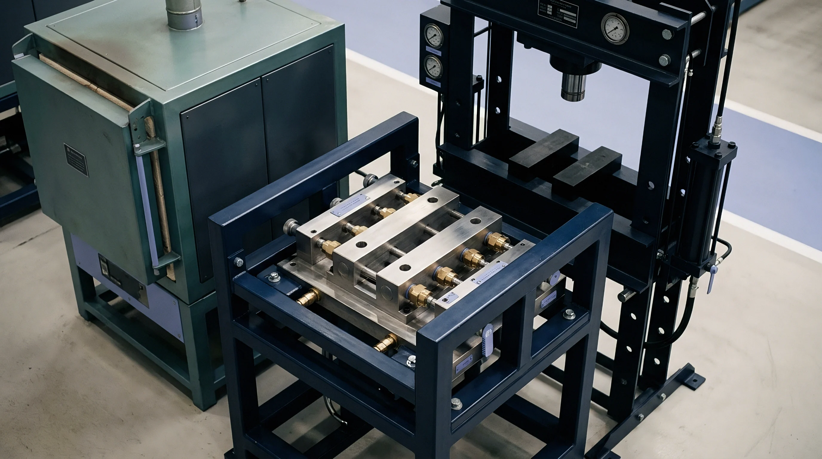
Plunger
Standard toggle clamps lack internal force regulation. As the toggle linkage crosses its mechanical dead center, kinematic mechanical advantage approaches infinity. Manual operator variation introduces wide load swings.
A heavy-handed operator exerts over 400 Newtons through a standard solid spindle, crushing plastic boss features. Calibrated spring plungers replace rigid threaded rods to isolate the part from operator grip strength.
Internal spring stacks govern the terminal force applied to the component. Helical compression springs or Belleville washer stacks sit housed within a cylindrical steel barrel threaded onto the clamp arm. As the clamp arm closes into its over-center locked position, the external spindle body advances while the internal plunger tip retracts, compressing the spring pack.
Terminal clamping force correlates directly with linear spring compression.
A Belleville spring pack stacked in alternating series doubles plunger travel while preserving linear load generation.
Plunger stroke travel must accommodate part-to-part wall thickness fluctuations. Injection moulded parts exhibit lot-to-lot wall thickness drift of plus or minus 0.08 mm due to thermal expansion of the tool steel, injection packing pressure variations, and regrind ratios. A rigid toggle spindle either over-clamps or fails to reach toggle lock when part thickness changes.
Calibrated spring plungers provide 5.0 mm to 10.0 mm of compliant axial travel, ensuring the clamp mechanism locks over-center while delivering a constant contact load.
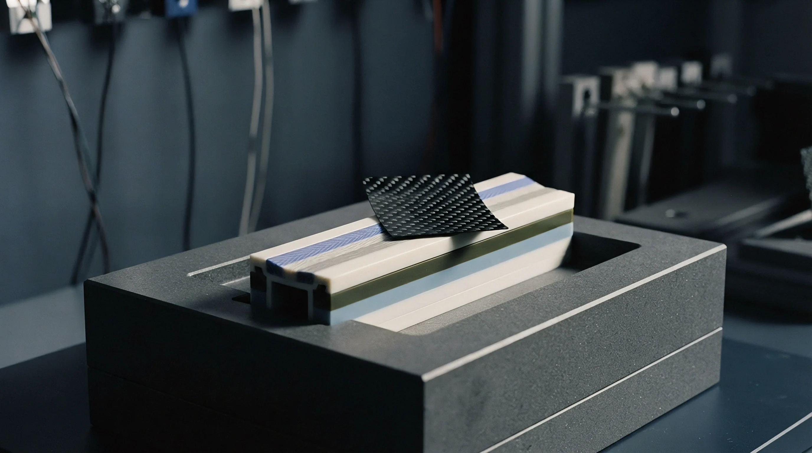
Mechanical Plunger Architecture
Internal construction dictates load linearity and cycle longevity. Plunger housings machined from 4140 chromoly steel feature fine internal bore finishes below 0.4 Ra micrometers to minimize sliding friction. The internal piston rides on a precision-ground shoulder screw, guided by a low-friction bronze bushing.
External metric threads, typically M12x1.5 or M16x1.5, permit axial positioning adjustments within the toggle clamp arm bracket.
- Plunger barrel threads directly into the toggle clamp arm to provide gross positional adjustment along the vertical z-axis.
- Belleville washer stack delivers non-linear high-load absorption within a compact cylindrical envelope.
- Sliding piston shaft transfers axial spring compression through a sealed linear guide bushing to prevent lateral cocking.
- Retaining collar restricts free plunger extension to establish an engineered preload state before contact.
- Contact tip interfaces with the moulded part surface using non-marring materials selected for cosmetic protection.
Contact tip materials govern surface mark prevention. Direct steel-on-plastic contact damages class-A aesthetic surfaces, leaving bright spots on textured polypropylene or cracking brittle acrylic lenses. Polyurethane tips with a 90 Shore A durometer provide traction without marring, though they degrade under prolonged oil contact.
Machined brass or polyetheretherketone tips provide rigid datum contact without galling painted surfaces. Toolmakers secure contact tips using threaded interchangeable stems, allowing quick replacement when tips wear or pick up particulate contamination.
Toggle linkage geometry requires careful positioning relative to the part normal vector. Plungers oriented at oblique angles generate lateral shear forces that displace the moulding laterally across the nest before vertical clamping occurs. Plunger centerlines align within two degrees of the datum face normal vector.
Angular alignment errors convert normal holding forces into lateral skidding forces, distorting locator pin holes and scratching cosmetic boundaries.
Suppliers often claim standard rubber-tipped spindles provide sufficient compliance for plastic parts, asserting that manual touch provides adequate force regulation across shifts.
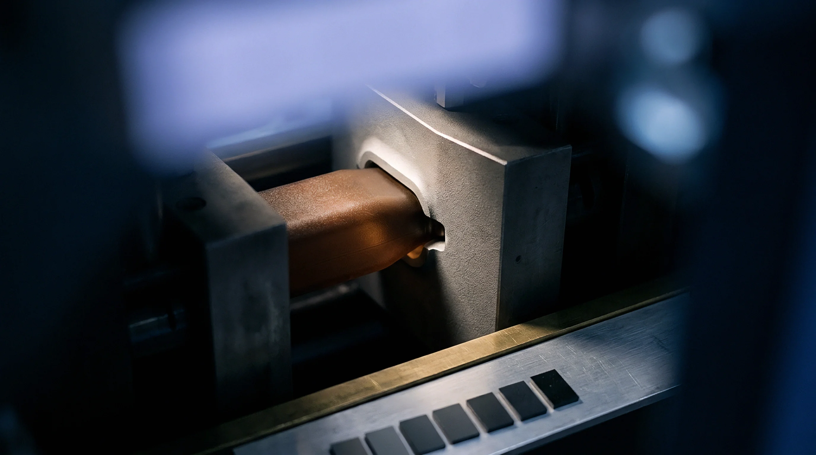
Calibration
Measurement integrity depends on verifying the exact force delivered by each plunger assembly. Periodic verification identifies broken internal springs, galling guide bushings, and altered preload settings. Quality technicians utilize portable load cell units equipped with digital readouts to verify clamp thrust right on the inspection bench.
The load cell rests on the fixture nest datum pad directly beneath the plunger tip, recording peak force as the operator closes the toggle clamp into its mechanical detent.
Spring fatigue alters plunger load over repeated production cycles. Helical springs lose free length after thousands of rapid actuations, shifting the operating force curve downward. Belleville washers experience edge wear, altering the stack deflection profile.
Fixture maintenance schedules specify plunger force verification at 5,000-cycle intervals or every three months. Documenting force values against upper and lower control limits prevents undetected load drift from corrupting CMM inspection programs.
| Clamp ID | Nominal Force (N) | Lower Limit (N) | Upper Limit (N) | Spring Stack Type | Preload Travel (mm) |
|---|---|---|---|---|---|
| TC-01 (Datum A1) | 25.0 | 22.5 | 27.5 | Single Helical | 3.2 |
| TC-02 (Datum A2) | 25.0 | 22.5 | 27.5 | Single Helical | 3.2 |
| TC-03 (Datum A3) | 35.0 | 31.5 | 38.5 | Parallel Belleville | 1.8 |
| TC-04 (Flange Hold) | 15.0 | 13.0 | 17.0 | Light Helical | 4.5 |
| TC-05 (Flange Hold) | 15.0 | 13.0 | 17.0 | Light Helical | 4.5 |
Adjusting plunger preload involves setting the internal piston position before clamp installation. Technicians loosen the lock nut on the plunger barrel, rotating the internal adjuster screw to achieve the specified initial spring compression. Bench testing on an arbor press verifies the preload displacement curve.
A force-versus-displacement test reveals mechanical binding inside the plunger barrel. If the force curve exhibits steps or erratic spikes exceeding ten percent of nominal load, the technician disassembles the unit to clean contamination or replace scarred piston shafts.
Linkage wear inside toggle clamps introduces mechanical play that alters plunger stroke. Toggle pins and stamped arm holes elongate over operational time, reducing the total travel transferred to the plunger body. A worn toggle clamp may fail to compress the internal spring stack to its calibrated depth, reducing applied force by twenty to forty percent.
Technicians measure total arm lash using a dial indicator during calibration rounds. Clamps exhibiting mechanical lash greater than 0.25 mm require replacement before recalibrating the plunger spindle.
Lockout paint applied across plunger adjustment threads ensures immediate visual detection of unauthorized tamper events.
Technicians mark verified plungers with stamped aluminum identification tags recording calibration dates, nominal force ratings, and expiration windows. In regulated environments, automated assembly cells integrate miniature piezo-resistive force sensors into the plunger tip or backup nest pad. Real-time load monitoring flags incomplete clamp engagement, missing parts, or double-moulding errors before automated sonic welding or laser cutting cycles begin.
The remaining question is whether shop floor temperature swings between unheated winter shifts and humid summer runs alter internal grease viscosity enough to skew dynamic plunger impact loads during rapid toggle closure.

Settlement
Disputes over part acceptance frequently trace back to fixture design discrepancies between the moulder plant and the customer assembly facility. When a moulder measures a moulding on a free-state CMM fixture while the receiving plant inspects the identical lot on a heavily clamped restrained fixture, dimensional reports diverge. Sourcing agreements must explicitly define the fixture architecture, locating scheme, and clamping force limits before cutting steel for inspection gauges.
Standardizing fixture designs across both manufacturing facilities eliminates unresolvable quality claim backlogs.
Gauge Repeatability and Reproducibility studies validate fixture stability prior to production part approval. Under typical AIAG MSA standards, a fixture must achieve a Repeatability and Reproducibility metric below ten percent of the total part tolerance band. Operator-to-operator reproducibility variation often stems from inconsistent manual toggle closure speeds.
Calibrated plungers mitigate this variation, reducing operator-induced gauge error to less than three percent of the total tolerance budget.
Financial responsibility for fixture maintenance and verification falls under tooling service contracts. Tooling budgets cover the base fixture fabrication, but ongoing preventative maintenance, plunger spring replacements, and load cell certifications represent operational expenditures. Clear tooling contracts define whether the moulder or the original equipment buyer covers annual calibration audits and physical wear repairs.
Neglecting these maintenance provisions leads to degraded fixtures that pass out-of-spec mouldings or reject acceptable components.
Per ASME Y14.5 section 4.20, drawings specifying restrained datum conditions must state the sequence and magnitude of restraining forces applied to each target area, and failure to document these parameters invalidates inspection rejections during formal commercial disputes.