Calculating Mold Insert Thermal Expansion for Injection Tooling
Calculating mold insert thermal expansion balances differential alloy growth to prevent parting line damage and core binding during warm operation.
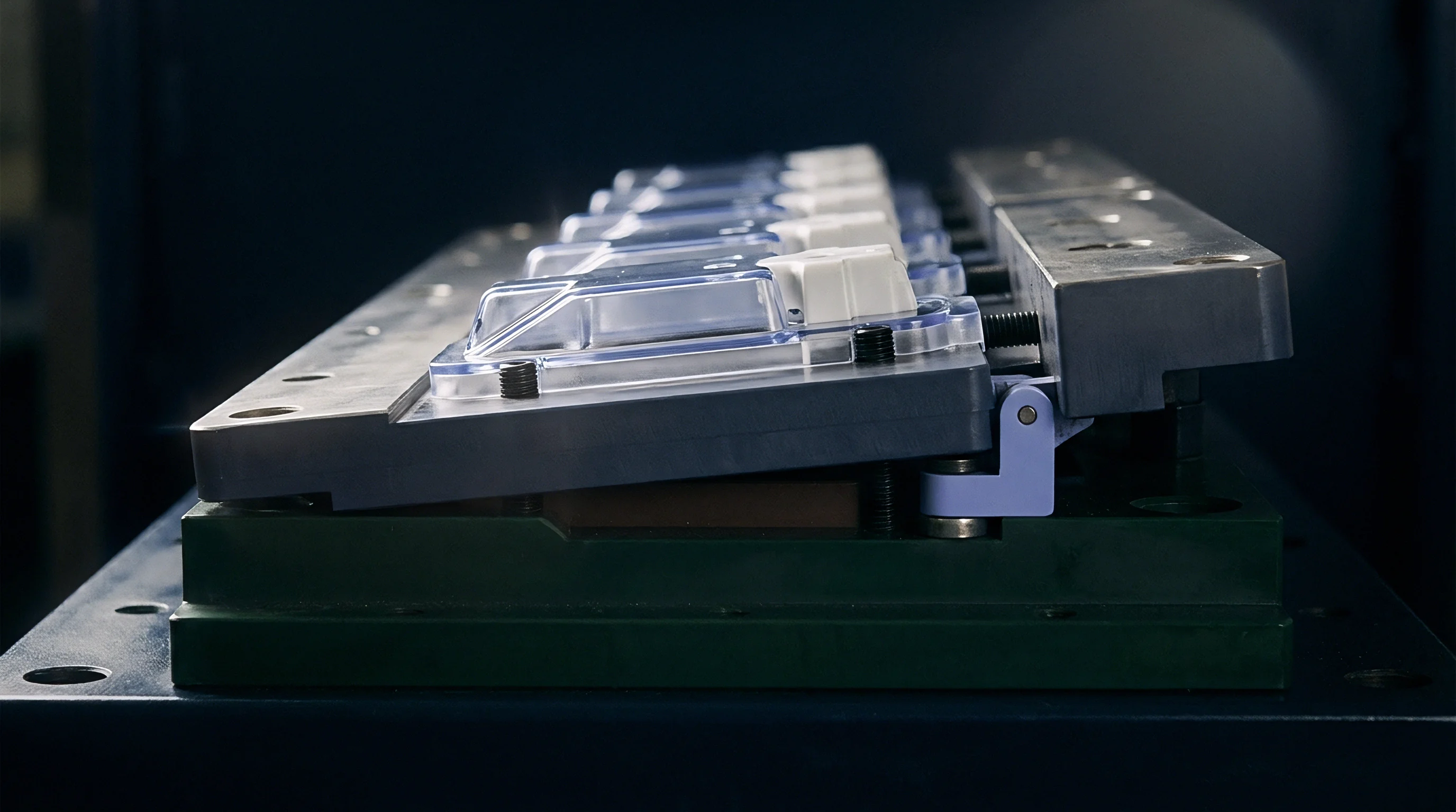
Swell
A steel core running at steady-state injection temperature occupies a larger volume than the tool drawer measurements recorded at ambient room conditions. When resin melt hits the cavity faces at 280°C, local surface temperatures spike within milliseconds before heat flows outward toward cooling channels. Steel expands into every unconstrained vector.
Outer dimensions push against pocket walls, tall cores extend along their axis toward the opposing cavity half, and mating shut-off faces compress against each other under press clamping force. Neglecting this expansion converts nominal side clearances into press-side interference.
Thermal stability requires several dozen continuous cycles. During startup, cold tool inserts receive high enthalpy input from successive melt injections while cooling fluid removes heat at a slower, bounded rate. Temperature rises until heat input per cycle balances thermal extraction through water lines, oil jackets, and ambient air radiation.
A tool block sitting at 20°C ambient shifts dramatically upon reaching its 80°C operating baseline. Linear growth across a 150 mm steel insert reaches nearly 0.1 mm under this temperature step. Toolmakers who machining pockets to tight slide-fit tolerances at ambient bench conditions discover that thermal growth locks moving cores and distorts parting line seals once heat saturates the assembly.
Thermal growth across unconstrained tool geometry follows isotropic expansion rules, while constrained inserts redirect linear displacement into internal compressive stress.
Differential growth drives the most severe tooling failures. Heat does not distribute evenly across mold plates. A core insert surrounded by deep polymer walls running an internal oil circuit at 140°C operates far hotter than the surrounding P20 cavity plate kept at 40°C by chilled water.
The hotter insert expands at a rate determined by its localized temperature field, while the cooler pocket resists that growth. Steel expands under heat. The resulting mechanical stress easily exceeds the yield point of unhardened tool steels, leading to permanent pocket deformation, localized galling, or sheared alignment pins.
Expansion affects part geometry directly through cavity sizing and parting line positions. Mold designers routinely apply polymer shrink factors to cavity dimensions, assuming the steel cavity retains its room-temperature nominal size during molding. In reality, the expanding cavity counteracts a fraction of the polymer shrinkage.
For high-precision technical components with tolerances under 0.02 mm, ignoring tool thermal expansion leads to out-of-spec parts despite perfect polymer shrinkage calculations. Tool drawings that lack cold-to-hot expansion compensations pass the error straight to the shop floor.
Tooling vendors often claim that thermal growth falls within standard machining tolerance bands and requires no explicit offset on detail drawings.
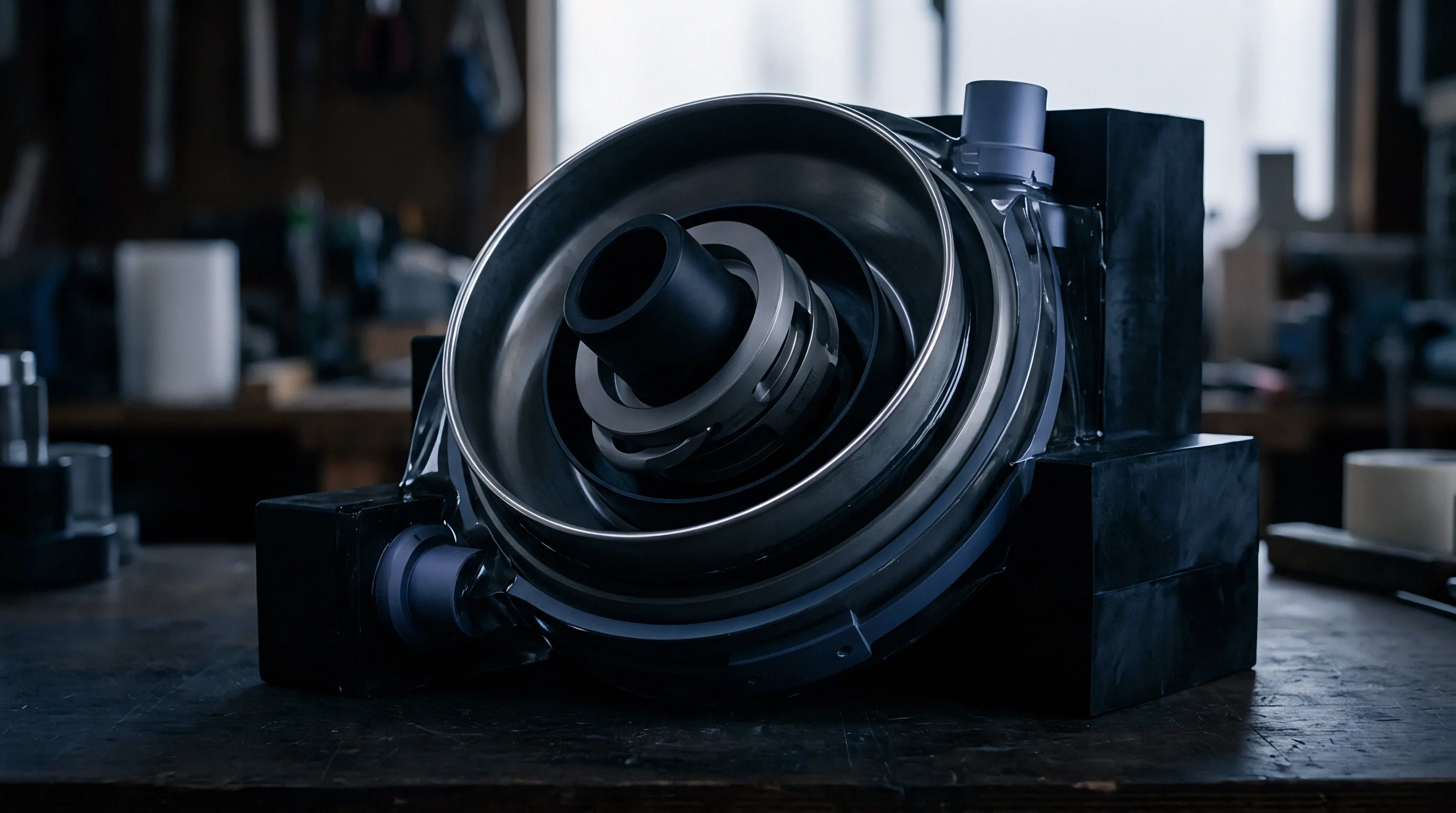
Metallurgy
Material selection dictates the rate and magnitude of dimensional changes across operating temperature ranges. High-alloy hot-work steels, stainless grades, and copper alloys expand at fundamentally different rates due to their crystal structures and chemical compositions. Tool steel selection balances wear resistance and toughness against thermal physical properties.
Choosing an insert alloy without evaluating its specific expansion profile creates mechanical conflicts when mated with standard mold base steels.
| Material Grade | Standard Designation | CTE (10⁻⁶ / K) | Thermal Conductivity (W/m·K) | Hardness Range (HRC) |
|---|---|---|---|---|
| 1.2344 / H13 | AISI H13 Premium | 11.8 | 24.5 | 48 – 52 |
| 1.2311 / P20 | AISI P20 pre-hardened | 12.8 | 29.0 | 28 – 32 |
| 1.2083 / 420 SS | AISI 420 Stainless | 10.5 | 19.0 | 48 – 52 |
| Ampco 940 | Nickel-Silicon Copper | 16.5 | 208.0 | 92 – 98 HRB |
| C17200 BeCu | Beryllium Copper Alloy 25 | 17.0 | 130.0 | 38 – 42 |
| Tungsten Carbide | WC-Co 12% | 5.2 | 80.0 | 88 – 92 HRA |
Hot-work tool steel 1.2344 exhibits a moderate mean coefficient of thermal expansion of 11.8 microns per meter per Kelvin between 20°C and 100°C. Martensitic stainless steel 1.2083 demonstrates lower expansion at 10.5 microns per meter per Kelvin, making it dimensionally stable but prone to thermal stress concentration due to low thermal conductivity. Copper alloys provide fast heat dissipation but present much higher expansion rates. Ampco 940 and beryllium copper expand at over 16.5 microns per meter per Kelvin.
Inserting a copper alloy core into an H13 pocket creates massive interference at elevated temperatures unless cold clearances account for the coefficient mismatch.
Carbide inserts present the opposite extreme. Cemented tungsten carbide features a thermal expansion coefficient less than half that of standard tool steel. High-wear locations, such as gate inserts or thin core pins, benefit from carbide durability.
However, an H13 plate expanding around a cold-fitted carbide insert opens up clearance gaps during warm production cycles. Loose gate inserts permit plastic melt leakage into backer plates, creating flash and ruining tool alignment. Mechanical fasteners or engineered clamping steps retain low-expansion materials inside high-expansion steel pockets.
A copper alloy core block expanding inside an H13 steel pocket creates 0.047 mm of differential growth per 100 mm of width across a 100°C thermal jump.
Failure modes in multi-material mold inserts stem from uncompensated thermal expansion misfits:
- Galling of sliding cores occurs when copper alloy slides expand laterally against steel guide rails, breaking down oil films and welding metal surfaces under high friction.
- Pocket wall cracking results from high-expansion insert materials expanding against internal corners of rigid tool plates without radial expansion gaps.
- Flash generation on parting faces develops when low-expansion inserts sink relative to surrounding steel blocks, opening parting line gaps under injection pressure.
- Dowel pin shear failures arise when thermal differential expansion forces multi-piece insert stacks sideways, applying high bending moments across precision locating pins.
Phase changes in tool steel heat treatment also shift permanent baseline dimensions before thermal expansion even occurs. Retained austenite transforms into martensite under thermal cycling, expanding the crystal matrix permanently over time. Double or triple tempering protocols stabilize tool steel microstructures, ensuring that dimensional shifts remain purely thermal and reversible.
Toolmakers select fully tempered steels to maintain predictable expansion behavior across millions of press cycles.
High thermal conductivity alloys lower surface temperature peaks but demand wider cold pocket clearances to absorb their aggressive bulk dimensional growth.

Calculus
Calculating tool growth requires precise definition of initial length, thermal expansion coefficients, and specific temperature differentials across assembly components. The foundational equation for linear thermal expansion calculates total dimensional change:
Δ L = L0 · α · (Toperating – Tassembly)
Here, L0 represents the nominal bench dimension at ambient calibration temperature, α is the mean coefficient of thermal expansion for the alloy within the target temperature band, Toperating is the steady-state working temperature of the insert, and Tassembly is the shop floor temperature during tool fitting, typically 20°C.
Multi-directional expansion calculations extend linear formulas into three orthogonal axes. Unconstrained rectangular inserts grow independently along length, width, and height. Volumetric growth approximates three times linear expansion for isotropic metallic alloys:
Δ V ≈ 3 · V0 · α · Δ T
Constraints inside rigid pocket cavities convert volume expansion into directional pressure. When pocket walls prevent sideways expansion, material displacement transfers entirely into the unconstrained height axis, magnifying axial growth beyond simple 1D linear predictions.
Differential growth calculations determine net movement between an insert and its housing block. The mathematical model subtracts plate expansion from insert expansion:
Δ Ldiff = L0 left
Consider a practical engineering calculation. A mold design incorporates a 120.000 mm long Ampco 940 copper alloy core insert fitted into an H13 steel cavity plate. Bench assembly occurs at 20°C. During molding of a glass-filled nylon grade, internal oil lines keep the copper insert at 110°C. Water cooling circuits hold the surrounding H13 cavity plate at 50°C.
- Calculate thermal expansion of the Ampco 940 insert across its length axis:
Δ Linsert = 120.000 · (16.5 × 10-6) · (110 – 20) = 0.1782 mm - Calculate thermal expansion of the H13 cavity pocket length:
Δ Lplate = 120.000 · (11.8 × 10-6) · (50 – 20) = 0.0425 mm - Determine the net growth mismatch inside the pocket:
Δ Ldiff = 0.1782 – 0.0425 = 0.1357 mm - Establish cold pocket length offset to achieve precise zero-clearance fit at operating temperature:
Lpocket, cold = 120.000 + 0.1357 = 120.136 mm

Can Thermal Gradients Overrule Static Growth Assumptions?
Temperature distribution across a mold core is rarely uniform. Heat enters continuously through the core tip exposed to plastic melt and leaves through internal cooling channels located several millimeters beneath the surface. This creates a steep thermal gradient along the length axis of the insert block.
Heat transfers through conductive steel following Fourier’s law:
q = -k · A · fracdTdx
Thermal gradient profiles convert uniform core geometry into slightly tapered shapes during operation. The tip of a tall core running at 160°C expands more than its base sitting near a 40°C cooling plate. Core growth calculations integrate local temperature fields along the axis to find true dimensional change:
Δ Ltotal = α int0H (T(x) – Tassembly) , dx
Applying finite element thermal analysis or segmented numerical integration yields exact shape predictions. A tall core pin experiencing a linear gradient from 140°C at the top face down to 40°C at the bottom clamp plate expands according to its average temperature of 90°C along its length, but expands radially based on localized temperature slices. Toolmakers grind draft compensation into cold core profiles to maintain vertical wall draft under severe operational gradients.
Accurate expansion calculations supply the initial offsets needed to model tool geometry before cutting steel on CNC machining centers.

Machining pocket geometry without thermal expansion compensations causes structural binding during thermal ramp-up. Insert blocks fit precisely inside cavity plates using tight transition or clearance fits defined under ISO tolerance systems. Fits designed for room temperature fail when components operate at different temperatures.
Establishing correct pocket gaps ensures easy tool assembly while maintaining zero-play alignment during steady-state molding cycles.
| Insert Material | Insert Dimension (mm) | Δ T Mismatch (°C) | Target Cold Clearance (mm) | ISO Fit Class (Bench) |
|---|---|---|---|---|
| 1.2344 / H13 Steel | 0 to 50 | 30 | 0.008 to 0.012 | H7/g6 |
| 1.2344 / H13 Steel | 50 to 100 | 50 | 0.020 to 0.030 | H7/f7 |
| Ampco 940 Copper | 0 to 50 | 60 | 0.035 to 0.045 | H7/e8 |
| Ampco 940 Copper | 50 to 100 | 80 | 0.080 to 0.100 | H7/d9 |
| Tungsten Carbide | 0 to 50 | 40 (Negative) | -0.005 to 0.000 | H7/p6 (Press fit) |
Locating methods maintain critical cavity positions despite dimensional growth. Dowel pins positioning an expanding insert must reside near the true geometric center of the block. Centered dowel placement distributes thermal movement symmetrically outward toward pocket walls, maintaining center-line alignment.
Off-center dowels push the entire block sideways during heat-up, throwing gate locations and core-to-cavity alignment out of true position.
DIN 16742 engineering guidelines require toolmakers to incorporate differential thermal expansion values directly into cold mold drawing tolerances prior to cavity cutting.
Tool designers follow specific rules when specifying pocket clearances and locating hardware for hot inserts:
- Center-line keying systems replace perimeter dowels on large rectangular inserts, allowing free radial expansion while fixing core center position.
- Corner relief radii inside milled pockets provide space for linear insert growth, preventing tight interference at sharp block corners.
- Belleville spring washers mounted behind insert clamp screws maintain constant seating tension while absorbing axial length changes.
- Side clearance pockets incorporate ground shim packs on non-datum faces, permitting quick press-side adjustment if thermal conditions change.
Calculated pocket gaps must never allow plastic melt penetration during warm operation. If cold clearance exceeds 0.03 mm under lower operating temperatures, low-viscosity resins such as polyamide 66 or liquid crystal polymers flow into side gaps, creating flash fins around insert perimeters. Flash traps inserts inside pockets, preventing removal during routine maintenance.
Designers balance cold clearance against warm shut-off requirements using precision thermal expansion math.
Tight pocket fitting without expansion allowance leads to plate warping, crushed dowel pins, and permanent galling along insert side walls.

Shutoff
Parting line shut-offs seal cavity spaces against high injection pressure. Press clamp force compresses mating steel faces together to prevent resin escape. Thermal growth along the core axis adds vertical height to inserts, increasing local contact pressure on shut-off faces.
An insert extending 0.04 mm higher than its surrounding cavity plate concentrates press clamping tonnage entirely on its small shut-off perimeter, crushing detail features and indenting opposing tool steel.
Pre-load calculations balance thermal expansion against mechanical elasticity under clamp load. Tool designers calculate required thermal height changes and establish cold insert stand-off heights, often termed land pre-load. Cold inserts protrude slightly above surrounding plate faces when cold.
Upon reaching operational thermal equilibrium, expansion matches plate growth and clamp compression, creating uniform contact pressure across the entire parting surface.
| Shut-off Type | Steel Hardness (HRC) | Cold Pre-load (mm) | Warm Operating Expansion (mm) | Net Shut-off Crush (mm) |
|---|---|---|---|---|
| Flat Face Perimeter | 48 – 52 | 0.010 to 0.015 | 0.020 | 0.005 to 0.010 |
| 7° Angled Interlock | 54 – 58 | 0.005 to 0.008 | 0.012 | 0.003 to 0.005 |
| 10° Core Shut-off | 58 – 62 | 0.000 to 0.005 | 0.015 | 0.002 to 0.004 |
| Copper Alloy Core Face | 38 – 42 (95 HRB) | 0.020 to 0.030 | 0.050 | 0.010 to 0.015 |
Angled shut-offs present complex multi-axis expansion challenges. Core interlocks with 5° to 10° draft angles experience both vertical height growth and horizontal width expansion. Vertical expansion pushes angled faces deeper into mating cavity pockets, multiplying normal contact forces.
The wedge effect converts axial expansion into massive radial forces capable of splitting cavity rings or galling guide angles.
Angled shut-off design applies trigonometry to calculate side clearance allowances. For an interlock angle thη, vertical growth Δ H generates normal movement Δ N against the opposing shut-off face according to:
Δ N = Δ H · sin(thη) + Δ W · cos(thη)
Where Δ W represents horizontal expansion of the core block. Standard tooling practices offset cold angled shut-off faces by grinding clearance back on non-datum side faces, ensuring smooth tool closure without scraping when thermal equilibrium is established.
Tooling drawings require clear annotation of cold bench dimensions alongside target warm operating sizes.
Does the calculated parting line pre-load account for press platen deflection under full clamping tonnage?
Reconciliation
Ignoring insert expansion during tool design generates immediate financial liabilities once tooling undergoes trials. Tooling modifications required to fix galling, flashing, or stuck cores consume toolroom hours, delay production start dates, and burn through budget reserves. Steel tool blocks recut to eliminate interference often require expensive laser welding, re-machining, or full insert replacement if too much metal was removed during initial bench adjustment.
Unplanned maintenance costs scale rapidly when thermally miscalculated tools run in mass production. Inserts running with insufficient pocket clearance build up internal shear stress, leading to fatigue cracking across thin mold ribs. Tool repairs performed press-side generate machine downtime charges that quickly exceed the original insert fabrication cost.
Sourcing agreements must assign clear financial responsibility for thermal design verification before tool design approval.
Procurement specifications protect buyers by demanding full thermal expansion audit documentation prior to steel cutting. Standard tooling contracts incorporate verification clauses that govern insert geometry approval:
Section 4.3 Tooling Thermal Compensation Clause ~ The toolmaker retains full responsibility for calculating and applying thermal expansion offsets for all mold inserts, core pins, and sliding elements operating above 60°C. Detail drawings must state nominal bench dimensions at 20°C, target operating temperatures, calculated material expansion values, and verified cold clearances. First article inspection acceptance under DIN 16742 Grade TG4 relies on parts produced at agreed operating thermal equilibrium, and any tool modification required to correct uncompensated thermal interference remains at the toolmaker’s expense.
Verifying expansion math before releasing drawings to the toolroom preserves capital, protects delivery schedules, and guarantees stable tool performance from T1 sample trials through full production runs.