Nested Variance Analysis in High Cavitation Tool Steel Qualification Protocols
Nested variance analysis isolates raw steel lot and heat-treat batch variation from hot runner imbalances to prove individual cavity Cmk capability before tool sign-off.


Structure
Hierarchical data collection isolates processing noise from tooling geometry in multi-cavity injection molds. High-cavitation tooling, running 32, 64, or 128 drops, presents a complex statistical challenge during qualification. Traditional single-factor process capability studies fail to distinguish whether a dimensional out-of-tolerance condition stems from raw steel variations, non-uniform heat treatment across insert blocks, localized runner thermal imbalances, or press-induced pressure fluctuations over time.
Nested variance analysis structures inspection data into a logical hierarchy that mirrors the physical architecture of the mold and its supply chain.
A standard process capability study pools all dimensional measurements into a single distribution. When applied to a 64-cavity tool, this flat pooling blends cavity-to-cavity geometric offsets with machine-level shot-to-shot drift. The resulting total variance obscures the true root cause.
A buyer evaluating such data risks rejecting a pristine tool steel lot due to an uncalibrated hot runner zone, or conversely, signing off on a tool with severe insert-to-insert machining discrepancies because press control was exceptionally tight during the qualification run.

Hierarchical Variance Breakdown in Multi Cavity Tooling
Data collected during first-article tooling trials reflects compounding sources of variation. Nested variance analysis breaks this scatter into discrete structural tiers. Steel moves.
The hierarchy starts at the raw material lot and cascades down to individual gage readings. Each tier represents a distinct potential failure mechanism in the tool fabrication and moulding workflow.
- Steel Melt Tier evaluates variance introduced by chemical segregation and grain size differences between raw steel heat lots supplied by the mill.
- Heat Treatment Tier isolates dimensional shifts originating from thermal gradients, quench rate variations, and phase transformations across vacuum furnace batches.
- Block Sub-Grouping Tier measures localized machining tolerances, EDM electrode wear, and plate distortion within multi-cavity insert pockets.
- Cavity Spatial Tier captures individual cavity profile errors, gate land variations, and core-to-cavity alignment offsets.
Structuring the experimental protocol along these nested levels allows quality engineers to calculate the exact variance component contributed by each tier. Heat alters dimensions. If the statistical breakdown reveals that seventy percent of total product variation resides at the heat treatment tier, re-machining cavity geometry will not bring the part into compliance.
The engineering effort must focus on thermal processing of the tool steel inserts.
A 64-cavity tool operating at a 6.8-second cycle time exhibits cavity-to-cavity dimensional variance that exceeds press-induced temporal variance by a factor of three when mold steel hardness varies by more than 1.5 HRC across insert blocks.
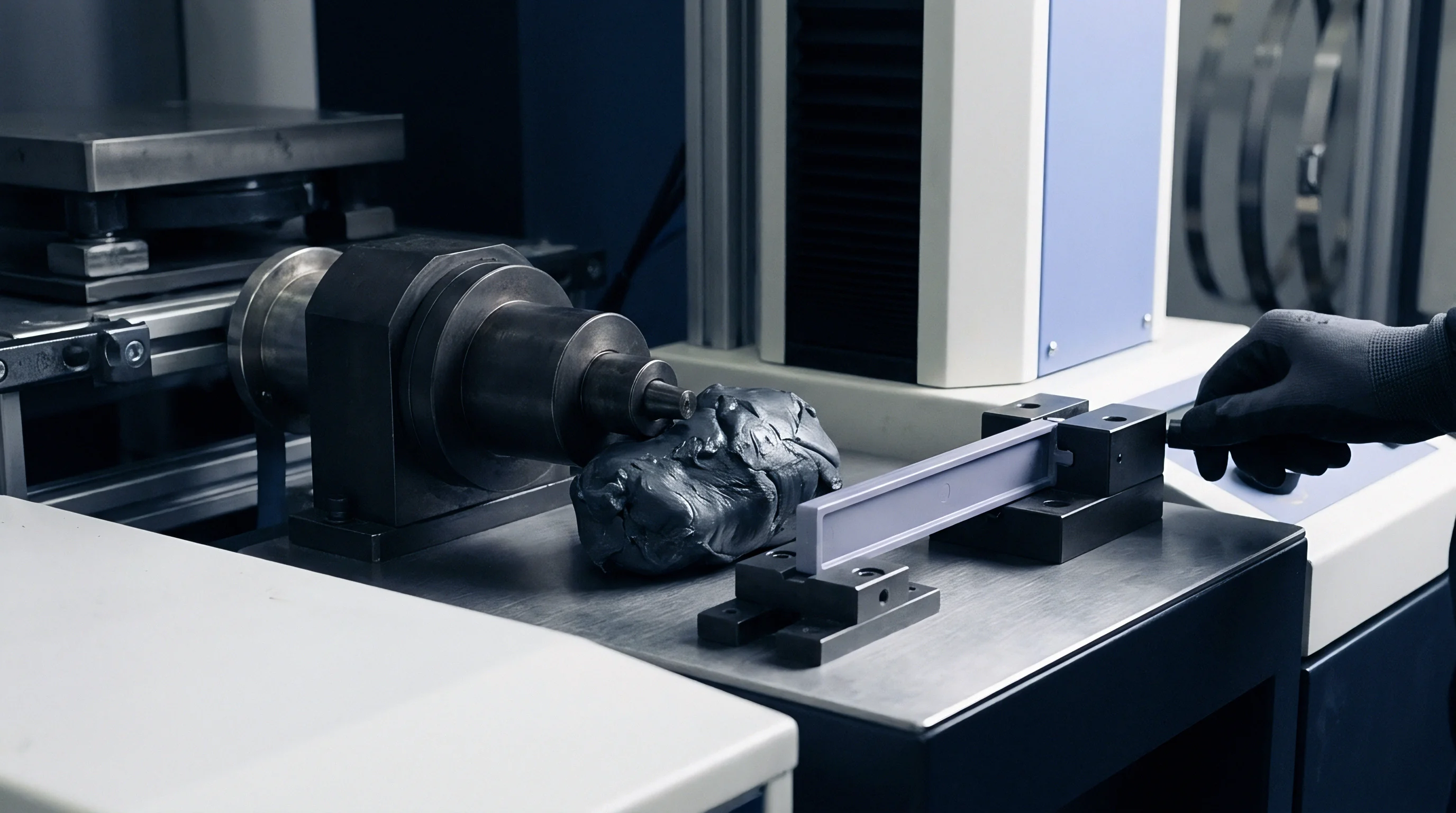
Sampling Geometry across Tooling Sub Blocks
Positioning test parts within a 64-cavity matrix demands systematic spatial mapping. High-cavitation tools rarely use a single monolithic cavity plate. Instead, toolmakers construct molds using modular sub-blocks, each housing four, eight, or sixteen cavity inserts.
Sampling plans that select parts at random across the mold face blur the boundary between sub-block machining errors and overall tool balance.
To implement a valid nested qualification, inspectors collect parts using a balanced spatial strategy. Five consecutive shots from a fully stabilized press run yield the baseline sample set. Parts are labeled by shot sequence, sub-block location, and specific cavity position.
Measurement protocols execute under strict temperature-controlled bench conditions to prevent inspection thermal expansion from inflating the residual error term.
| Variance Tier | Physical Root Cause | Sampling Strategy | Target Variance Contribution |
|---|---|---|---|
| Steel Heat Lot | Carbide segregation, ingot inclusions | 3 steel melt heats certified via EN 10204 3.1 | Less than 5 percent total variance |
| Thermal Processing | Quench rate delta, micro-cracking, residual stress | 4 vacuum furnace heat-treat loads | Less than 10 percent total variance |
| Insert Sub-Block | CNC milling tolerances, electrode wear, wire EDM drift | 8 cavity blocks per mold plate | Less than 15 percent total variance |
| Cavity Position | Gate land wear, cooling channel proximity, core offset | 64 individual cavity locations | Less than 60 percent total variance |
| Temporal Process | Melt viscosity shifts, hydraulic pressure drift | 10 consecutive press cycles over 4 hours | Less than 10 percent total variance |
Failure to isolate structural variance tiers leads to misplaced tooling adjustments. Toolmakers spend tens of thousands of dollars micro-milling individual cavity steel to fix dimensional spreads that actually stem from non-uniform heat treatment across sub-blocks. This misdiagnosis extends qualification lead times by months, inflates landed tooling costs, and produces mold inserts that fail prematurely from excessive thermal cycling stress.

Quench
Thermal treatment of mold inserts creates microscopic hardness gradients across large tool steel billets. High-cavitation tooling relies heavily on premium tool steel grades such as DIN 1.2343 (H11 ESR), DIN 1.2083 (420 ESR), Bohler M333 ISODUR, and Uddeholm Stavax ESR. Achieving consistent dimensional stability across a 128-cavity tool requires every cavity insert to respond identically to electrical discharge machining, polishing, and plastic melt erosion.
During vacuum heat treatment, sub-surface regions of large steel blocks experience lower quench cooling rates than outer corners. This differential thermal history alters the balance of tempered martensite and retained austenite. When steel inserts undergo final grinding and EDM wire cutting, relaxation of asymmetric internal stresses induces micro-warpage.
Sub-micron variations in insert dimensions compound across multi-cavity plate assemblies, resulting in uneven clamping force and localized resin flash.

Carbide Distribution and Segregation in ESR Tooling Steels
Electro-slag remelted alloys reduce non-metallic inclusion bands compared to standard air-melted grades. Primary alloy carbides can still segregate along central ingot lines during ingot solidification. In heavy cross-section billets destined for multi-cavity block inserts, carbide stringers disrupt local thermal conductivity and micro-machinability.
Steel hardness shifts microstructures. Machining 64 identical cavity pockets into an insert block cut from a segregated steel billet yields varying surface finishes and micro-dimensional offsets. Cavities located along the core axis of the original steel ingot show elevated tool wear rates during high-speed CNC milling.
The resulting dimensional variance manifests as a nested effect tied directly to raw material steel geometry.
Sintered powder metallurgical tool steels processed under NADCA 207 standards restrict micro-segregation to Rating 1 to prevent differential EDM spark wear across adjacent cavity pockets.

Dimensional Shifts from Heat Treatment Residual Stresses
Volumetric expansion during martensitic transformation generates internal stress distributions. High-cavitation inserts require multi-stage stress relieving and deep cryogenic treatment at minus 180 degrees Celsius to convert retained austenite into stable martensite. Omitting sub-zero treatment leaves up to eight percent retained austenite in high-chromium stainless tool steels like DIN 1.2083.
Retained austenite transforms into un-tempered martensite during production thermal cycling. This phase change causes progressive dimensional swelling of cavity inserts over hundreds of thousands of cycles. Cavities vary by design.
When individual inserts come from different heat treatment batches, rate of expansion varies by cavity block, introducing operational variance into production runs long after initial tool sign-off.
- Primary Segregation Bands cause localized hard spots that alter wire EDM spark gap distances across adjacent insert pockets.
- Retained Austenite Swelling drives un-predicted core pin growth during sustained mold temperatures above 80 degrees Celsius.
- Sub-Surface Soft Core leads to cavity sidewall indentation under peak injection pressures exceeding 1500 bar.
- Differential Grain Growth produces variable surface polishability between cavity blocks treated in separate furnace cycles.
- Asymmetric Quench Strain warps multi-cavity retainer plates, forcing core pins out of concentric alignment with cavity gates.
Tool steel vendors often attribute cavity-to-cavity dimensional variations to press-side melt temperature control rather than acknowledging batch-to-batch hardness spreads in supplied insert blocks.
Balance
Fluid dynamic variation inside hot runner channels distorts melt temperature and shear history. In 32, 64, and 128-cavity hot runner systems, resin travels through complex, branched flow channels. Even when runner geometry appears perfectly symmetrical on CAD drawings, non-Newtonian polymer melt behavior introduces severe thermal and viscosity imbalances between inner and outer cavity groups.
High shear rates near channel walls heat the outer polymer layers, while the central melt core remains cooler. At artificial runner junctions, this sheared material partitions unequally into downstream branches. The phenomenon, known as shear-induced thermal imbalance, delivers hotter, less viscous polymer to specific cavity clusters.
Hotter resin fills cavities faster and exhibits higher volumetric shrinkage, establishing a systematic, position-dependent dimensional variance tier within the tool.
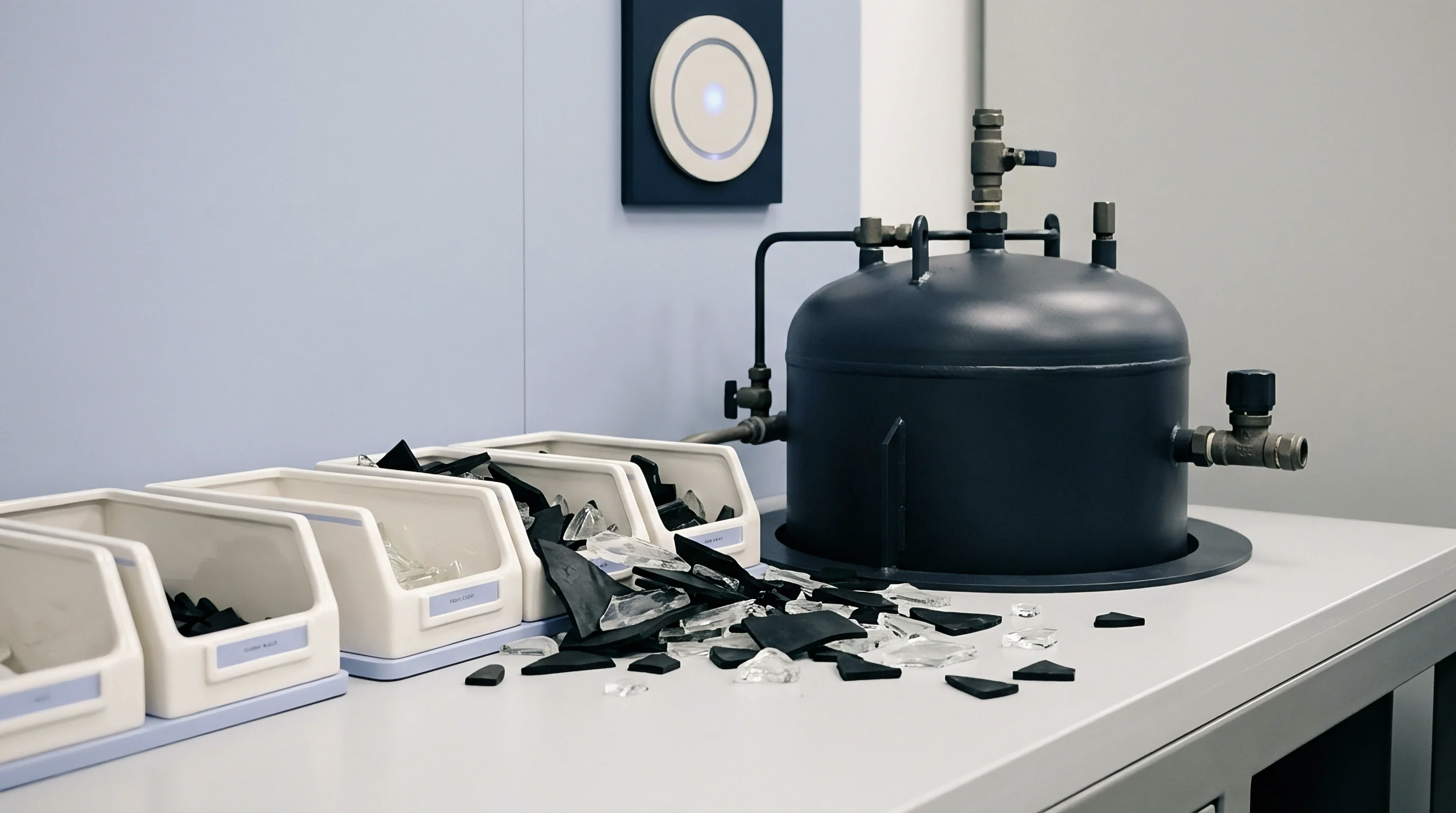
Rheological Asymmetry in Multi Branch Runner Manifolds
Non-Newtonian shear thinning causes polymer melt to partition unevenly at every runner junction. In a standard 64-cavity geometric layout, outer cavities receive resin that has experienced different total shear energy compared to central cavities. Viscosity drives peak pressure.
The resulting melt temperature variations reach up to 15 degrees Celsius between drops on the same hot runner manifold.
Temperature shifts alter cavity packing efficiency. Cavities fed by hotter runner branches experience higher effective end-of-fill pressure and prolonged gate seal times. Consequently, parts produced in inner cavity clusters display significantly different wall thicknesses, tight-tolerance diameters, and sink mark depths than parts molded in peripheral cavities.
This variance originates in runner physics rather than cavity steel machining tolerances.
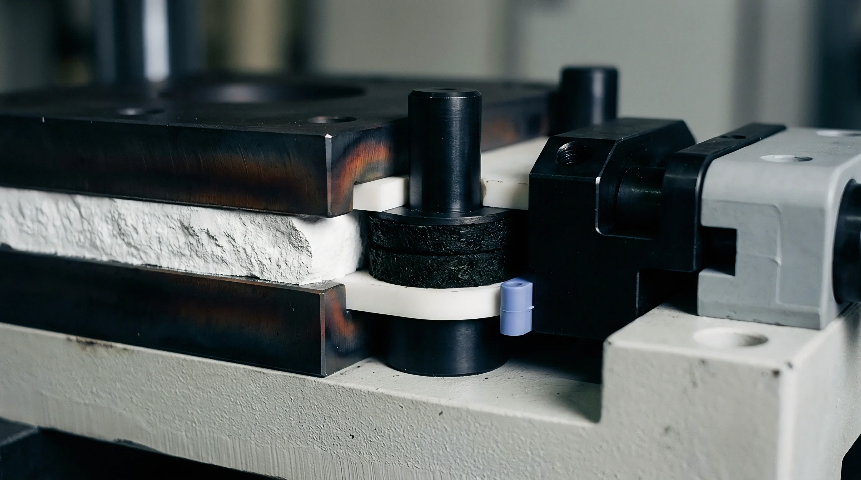
Does Runner Symmetry Guarantee Cavity Consistency?
Geometric symmetry in runner layouts fails to guarantee identical filling across all drops. Melt rotation technology, such as specialized runner insert geometries that physically flip sheared melt layers before branching, must be incorporated into manifold design to eliminate thermal asymmetry. Mold temperature governs shrink.
Without melt rotation, inner and outer cavity groups operate under fundamentally different processing windows.
| Manifold Region | Melt Temp Delta (°C) | Peak Cavity Pressure Spread (bar) | Volumetric Shrinkage Delta (%) | DIN 16742 Tolerance Class Achievable |
|---|---|---|---|---|
| Primary Drop (Center) | Baseline (+0.0) | Baseline (750 bar) | 1.85 % | TG4 (Tighter) |
| Secondary Branch (Mid) | +4.2 °C | -35 bar | 1.98 % | TG4 |
| Tertiary Branch (Outer) | +11.8 °C | -85 bar | 2.22 % | TG6 (Looser) |
| Corner Drop (Extreme) | +14.5 °C | -110 bar | 2.35 % | TG7 |
Hot runner temperature controller zone layouts also contribute to nested spatial variance. Grouping multiple drops onto a single thermocouple heating zone prevents precise localized thermal tuning. Individual nozzle tip wear, heater band aging, and thermal bridging between manifold and top clamping plate create persistent, static cavity variance patterns that override press-side process adjustments.
Melt viscosity shifts of ten percent alter flow balance across tertiary runner branches before cavity pressure sensors detect the injection peak.
A rule of thumb dictates that inner cavities shrink more than outer cavities whenever hot runner shear distribution remains uncorrected.

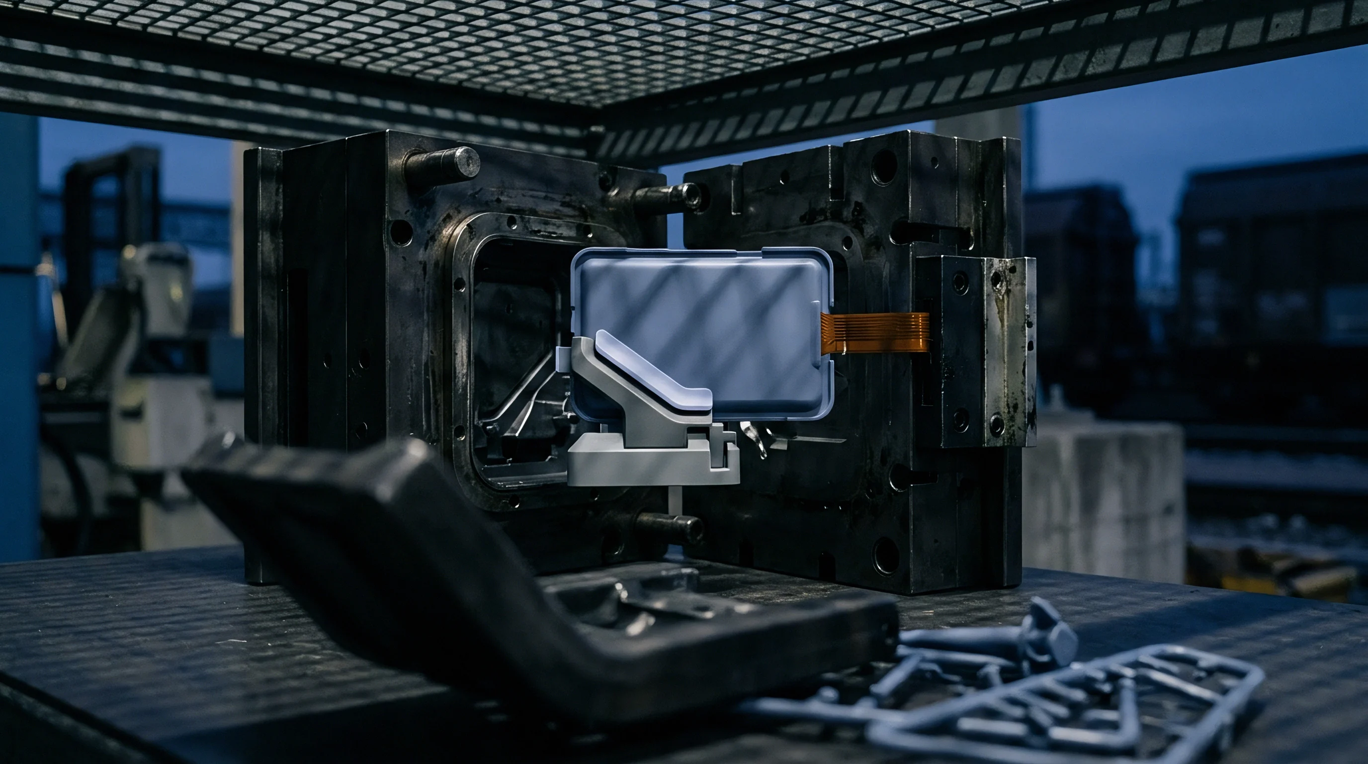
Arithmetic
Statistical decomposition splits total observed scatter into nested variance components. Nested Analysis of Variance (ANOVA) utilizes a hierarchical mathematical model to partition total sum of squares into independent factors. For a qualification protocol evaluating steel heat lot, insert block, cavity position, and temporal press variation, the statistical model takes the explicit hierarchical form:
Y_ijklm = mu + S_i + B_j(i) + C_k(ij) + T_l(ijk) + e_m(ijkl)
Where Y represents the observed dimensional measurement, mu is the overall mean dimension, S_i represents the random effect of steel heat lot i, B_j(i) is the effect of insert block j nested within steel lot i, C_k(ij) is the effect of cavity k nested within block j and steel lot i, T_l(ijk) is the temporal process variation of shot l nested within cavity k, and e_m is the residual gage measurement error.

Decomposing Nested Sum of Squares for Hierarchical Tooling
Mathematical separation of variance begins by structuring raw dimensional measurements into a tree. Measurements carry error. The total sum of squares (SST) partitions into component sums of squares representing each level of the nesting hierarchy.
Degrees of freedom follow the sample allocation across steel lots, sub-blocks, cavities, and repeat injection shots.
Calculating Expected Mean Squares (EMS) dictates how statistical F-tests are constructed. In a nested model, lower-level terms serve as denominators for higher-level F-tests. Cavity four leads shrink.
For example, testing the significance of insert block variance requires dividing the Block Mean Square by the Cavity Mean Square, not by the residual error mean square. Using the wrong error term in F-ratio calculations leads to false claims of statistical significance.
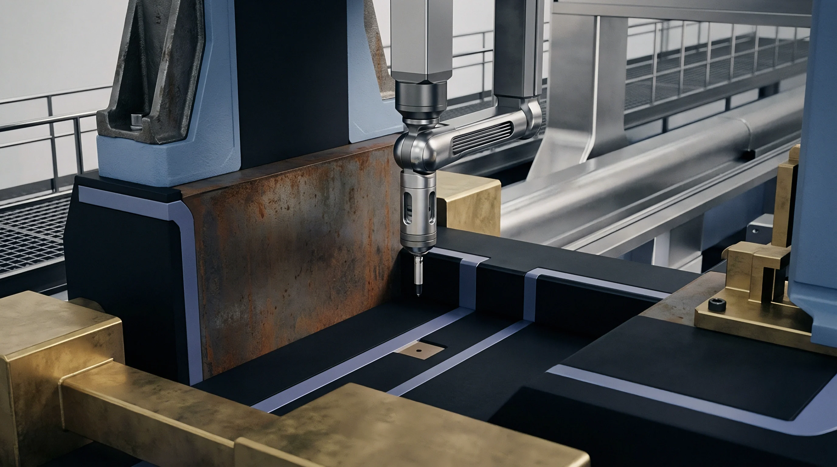
Worked Example for a Sixty Four Cavity Tool
A qualification protocol evaluates 64 cavities grouped across four steel insert blocks cut from two distinct raw steel melt heats. Five consecutive shots are measured using a automated optical coordinate measurement machine, taking two replicate readings per part to isolate gage error.
- Calculate the mean dimension for every cavity across all five press shots and replicate gage measurements.
- Compute the sub-block mean dimensions by averaging all cavities contained within each of the four discrete insert blocks.
- Determine the steel melt lot means by pooling sub-block averages corresponding to heat lot A and heat lot B.
- Calculate the Sum of Squares for Steel Heats (SSS), Sub-Blocks within Heats (SSB), Cavities within Sub-Blocks (SSC), Shots within Cavities (SSTemp), and Pure Measurement Error (SSE).
- Divide each Sum of Squares by its corresponding degrees of freedom to obtain Mean Squares (MS).
- Derive the individual variance components (sigma squared values) by solving the system of linear equations generated from the Expected Mean Square formulas.
Data proves the offset. In this scenario, raw measurement calculations yield an overall standard deviation of 0.018 millimeters across all 640 inspection data points. Flat capability analysis calculates a total process capability Cpk of 0.92 based on a target tolerance of plus or minus 0.050 millimeters, indicating an unacceptable tool.
Nested variance decomposition reveals the true structure of the scatter: variance component for steel lot equals 0.000004 mm squared, sub-block variance equals 0.000012 mm squared, cavity variance equals 0.000280 mm squared, temporal process variance equals 0.000018 mm squared, and gage error equals 0.000002 mm squared.
Cavity capability metrics calculated without nested variance decomposition mask systemic steel hardness variation by pooling it into residual random noise.
The arithmetic demonstrates that eighty-six percent of total dimensional variance resides specifically at the cavity-within-block tier. Temporal press variation contributes less than six percent. Tooling engineers can now target core pin grinding and gate land erosion on specific outlier cavities rather than adjusting press holding pressure or requesting new raw steel heats.
Recalculating potential tool capability after correcting the top six outlier cavities raises the tool Cpk to 1.48, fully qualifying the steel housing assembly for volume production.
Isolating the variance components establishes a quantitative roadmap for steel rework. Tooling modifications execute only on cavities where individual mean offsets exceed three times the square root of the residual variance term. The press holds pressure.
The math directs steel removal precisely where tool geometry deviates from nominal, preserving original steel coatings and preventing unnecessary cavity modification.


Contract
Commercial agreements for high-cavitation tooling demand objective statistical gates before final payment release. Tooling quotes land late. Sourcing contracts that base tool sign-off on a simple flat process capability study risk accepting high-cavitation tools with latent structural defects.
Once a buyer signs off on a tool based on overall pooled Cpk, financial responsibility for cavity rework and scrap allocation transfers entirely from the toolmaker to the buyer.
A buyer-side tooling contract must incorporate nested variance qualification protocols directly into the purchase order terms. Specifying DIN 16742 tolerance groups alongside explicit nested variance component thresholds protects the buyer against uneven multi-cavity performance. Sourcing agreements must explicitly define statistical acceptance criteria for overall tool capability (Cpk) versus individual cavity capability (Cmk).
Acceptance Criteria in High Cavitation Tooling Sign Off
Formal verification protocols define the minimum process capability metrics for tool transfer. Contracts must stipulate that no individual cavity Cmk value fall below 1.67 during a continuous four-hour T1 trial, even if total tool Cpk meets the standard 1.33 threshold. This dual-gate requirement prevents toolmakers from hiding bad cavities behind exceptionally tight press control during short qualification runs.
Raw steel documentation forms a non-negotiable part of the qualification dossier. Inspection protocols require EN 10204 type 3.1 chemical analysis certificates, ultrasonic testing reports according to SEP 1921, and micro-cleanliness certification under ISO 4967 for all cavity and core insert blocks. Failure to provide mill certifications prior to steel cutting voids lead-time penalty exclusions in the primary tooling agreement.

Cavity Quarantine and Steel Lot Replacement Protocols
Isolating non-conforming cavity pockets protects overall tooling yield during high-volume production. When nested variance analysis reveals that a specific insert block exhibits structural dimensional offsets exceeding twenty percent of total tolerance, formal quarantine protocols initiate. Sourcing agreements dictate whether the toolmaker re-machines existing steel or replaces the entire insert block from a new certified steel melt lot.
| Qualification Phase | Variance Component Threshold | Standard / Protocol Reference | Financial Ownership of Rework |
|---|---|---|---|
| Steel Cert Gate (T0) | Zero non-metallic inclusions > Class 2 | EN 10204 3.1 / ISO 4967 | Steel Mill / Distributor |
| First Article (T1) | Cavity variance component | DIN 16742 TG4 / ISO 22514-7 | Toolmaker / Mold Builder |
| Process Window (T2) | Temporal variance component | Scientific Molding / ISO 294 | Part Moulder / Setter |
| Final Sign-Off (T3) | Cmk >= 1.67 all cavities, Cpk >= 1.33 | VDA 4 / AIAG SPC Manual | Buyer Payment Release |
Financial liability clauses allocate costs based on the variance breakdown derived during qualification trials. If nested variance calculations prove that dimensional failure stems from hot runner shear imbalance, the manifold manufacturer absorbs the cost of runner redesign and insert replacement. If the variance traces back to soft steel cores resulting from inadequate vacuum furnace quenching, the heat treatment supplier covers re-machining charges and trial resin expenditures.
Standard supply agreements incorporating ISO 22514-7 statistical procedures compel toolmakers to warrant cavity-to-cavity variance below thirty percent of total drawing tolerance over one million injection cycles.
Incorporating explicit nested variance limits into the purchase order guarantees that tool steel qualification relies on physical engineering evidence rather than supplier optimism. Buyers retain full contractual leverage to withhold final tooling payments until variance component analysis demonstrates that every individual cavity satisfies dimensional capability requirements under production conditions. Per standard tooling terms, failure to satisfy cavity-level Cmk thresholds within ninety days of initial T1 sampling authorizes the buyer to reject the mold assembly, cancel the purchase order without penalty, and demand full reimbursement of advance payments.