Analyzing Gas Compression Dynamics in Micro Textured Mold Surfaces
Micro-cavity air undergoes adiabatic compression during injection, requiring active vacuum or porous venting to prevent dieseling and ensure feature replication.
Breach
Trapped gas inside micro-cavities stops the melt front long before the machine hits its mechanical stroke limits. In standard macroscopic cavities, air escapes through parting planes or ejector clearances between 0.02 mm and 0.05 mm. But when surface texturing introduces features below 50 μm with aspect ratios over 1.5, standard parting clearances cannot evacuate those micro-volumes fast enough.
The advancing melt acts like a hydrodynamic piston, sweeping air into blind features and compressing it into high-temperature thermal barriers. Tool steel at the feature tip experiences localized thermal spikes, while the melt solidifies prematurely against sudden backpressure.
Compression speed depends directly on injection velocity. When front velocities exceed 150 mm/s in thin-wall executions, evacuation time for a 20 μm deep micro-groove drops below 300 μs. Trapped inside these micro-structures, air cannot escape through the primary venting network and undergoes near-adiabatic compression.
Pressure climbs rapidly from an atmospheric baseline to dozens of megapascals. The resulting thermal flash frequently surpasses the resin’s thermal decomposition threshold, leaving behind dieseling, soot contamination, or internal voids.
Mould builders often confuse primary cavity evacuation with micro-texture venting. Macro vents clear air pushed ahead of the main melt front along runners and primary ribs, but they do nothing for air trapped below the nominal parting plane in isolated micro-wells. When optical structures, superhydrophobic pillars, or tactile grains fail replication checks, process technicians typically raise hydraulic pack pressure.
That adjustment accomplishes little: the trapped air acts like a stiff pneumatic spring, so higher pack pressure simply compresses the bubble into a smaller volume while raising its peak temperature.
The buyer signs for steel that fails to hold replication metrics across a full shift. Toolmakers regularly point to resin viscosity or batch variability, but the flaw lies in the venting dynamics of the micro-texture array. Tooling geometry defines the gas compression path, setting the line between true feature replication and scrap.
Thermodynamics
Gas behaviour inside a blind micro-cavity follows polytropic compression paths shaped by injection velocity and heat transfer into the surrounding tool steel. The interplay between transient gas pressure, trapped volume, and absolute temperature ultimately determines whether polymer fills the feature or burns the mold.
Polytropic Exponents in Micro Scale Compression
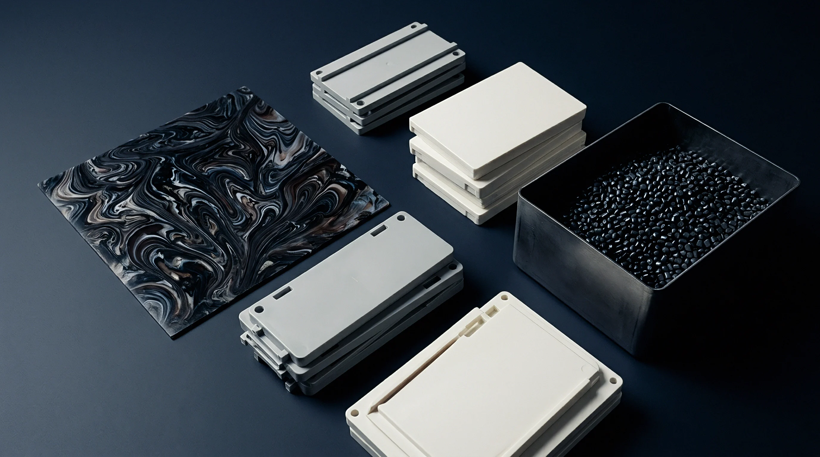
The compression rate dictates the effective polytropic exponent, n, in the path equation P multiplied by V to the power of n equals a constant. When the melt front approaches micro-features slowly ~ under 10 mm/s ~ the process stays nearly isothermal, holding an exponent close to 1.0 as heat conducts into the steel. At commercial speeds above 100 mm/s, filling times collapse to microseconds and the exponent shifts toward the adiabatic limit of 1.4 for diatomic gases.
Air compressed from 0.1 MPa to 8 MPa under near-adiabatic conditions reaches theoretical temperatures exceeding 800 K in less than 400 microseconds.
Polymer degradation occurs rapidly under these thermal spikes. Polycarbonate degrades above 610 K, and Polymethyl Methacrylate begins side-chain cleaving near 530 K. High-speed compression converts mechanical energy straight into thermal energy within the gas. Dieseling is more than a cosmetic stain: it bakes carbonaceous residue onto micro-cavity sidewalls, permanently altering surface roughness and ruining part release.
Heat Transfer across the Gas Boundary
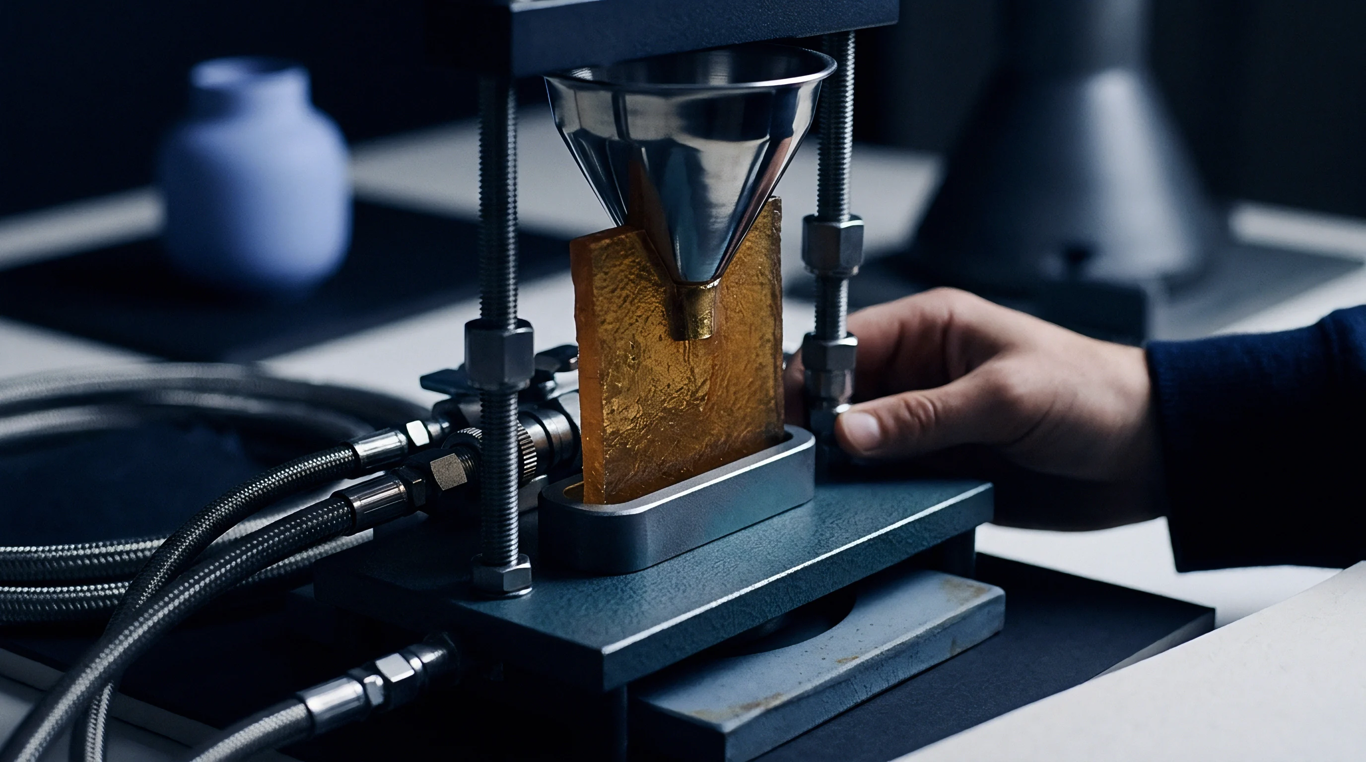
Thermal diffusivity in the tool substrate caps how quickly the compressed gas bubble can cool. Hardened tool steels such as 1.2343 or 1.2083 offer thermal conductivities between 24 W/(m·K) and 29 W/(m·K), whereas Beryllium-copper inserts reach 130 W/(m·K) to dissipate localized compression heat much faster. Even so, heat flux across the pocket remains bottlenecked by air’s conductivity, which sits below 0.04 W/(m·K) even under pressure.
The temperature jump where trapped air meets the melt front alters local polymer rheology. While bulk melt temperature stays constant, the thin skin contacting hot air experiences a transient thermal surge. That momentary heat drop reduces local viscosity, but opposing pneumatic backpressure counteracts any flow advantage.
Because trapped air resists displacement, feature apexes freeze with rounded profiles instead of sharp micro-prisms.
| Injection Front Velocity (mm/s) | Effective Polytropic Exponent (n) | Peak Transient Pressure (MPa) | Calculated Peak Gas Temp (K) | Observed Replication Ratio (%) |
|---|---|---|---|---|
| 15 | 1.08 | 1.8 | 375 | 91 |
| 50 | 1.19 | 4.2 | 480 | 84 |
| 120 | 1.31 | 8.7 | 680 | 63 |
| 250 | 1.38 | 14.5 | 890 | 38 |
High injection velocities cause steep drops in replication fidelity. Overcoming this thermodynamic barrier requires physical relief channels or active evacuation built into the tool design.

Geometry
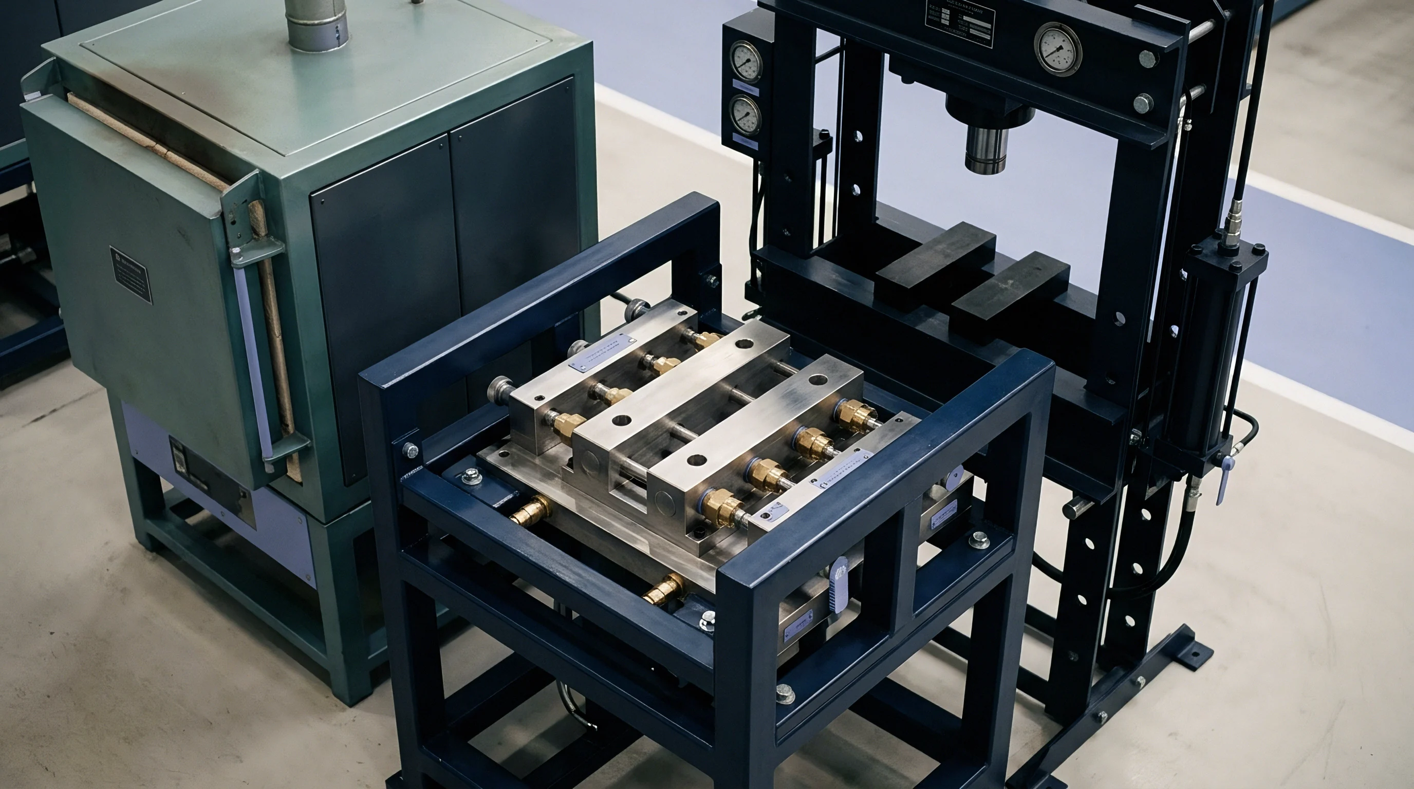
Feature orientation, aspect ratio, and layout density determine whether air vents freely or locks into pressurized cells. Micro-textured surfaces follow two structural topologies: continuous network channels and isolated cellular wells. Each presents distinct flow mechanics requiring different tooling allowances.
Continuous Channels versus Discrete Pockets
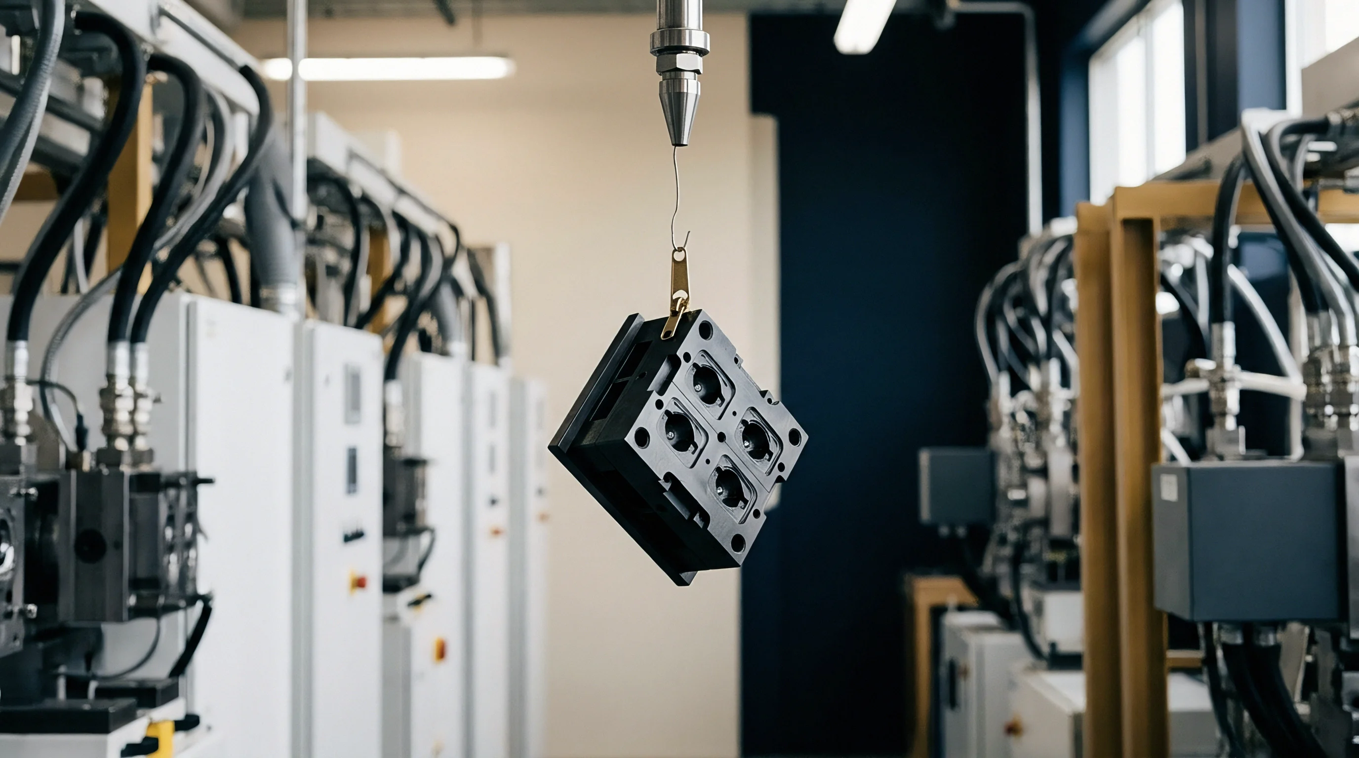
Grooves aligned with the melt flow let advancing plastic push air along the channel toward primary vents. Perpendicular channels produce transverse fingering: the polymer crest bridges across rib tops and seals air pockets at the bottom. Isolated micropillars or dimples trap air immediately regardless of orientation as soon as the melt contacts the surrounding lands.
Aspect ratio dictates resistance to complete filling. When feature depth divided by width exceeds a ratio of 1.2, surface tension and viscous drag impede entry, and trapped air at the root cannot dissolve during the short cycle time. Zero-draft micro-pillars lock air along vertical sidewalls.
Adding draft angles between 1.5 degrees and 3 degrees improves demolding and gives escaping air a conical path to slip up the sidewalls before the melt closes the perimeter.
- Flow Angle Misalignment creates asymmetric filling fronts that seal the down-flow side of micro-textures, blocking passive venting along parting lines.
- High Feature Aspect Ratio increases pneumatic backpressure exponentially, forcing holding pressures high enough to cause macro-perimeter flash.
- Excessive Texture Density reduces land area between features, weakening steel support ribs past critical beam deflection limits.
- Abrupt Wall Transitions trigger localized flow separation, trapping air voids at sharp internal radii.
Femtosecond laser ablation creates fundamentally different surface profiles than chemical etching. Chemical etching leaves spherical, undercut cavities that catch gas bubbles at re-entrant corners. Laser etching produces grooves with controllable sidewall tapers, which must match melt front curvature to expel air cleanly.
Relief
Eliminating trapped gas requires targeted tool modifications right at the feature boundary rather than relying on random steel porosity. Effective evacuation uses engineered porous inserts, sub-venting channels, or controlled vacuum extraction.

Can Passive Evacuation Clear High Density Grooves?
Passive evacuation using porous sintered metal works only when pore sizes match resin rheology. Sintered steels with pore ratings between 3 μm and 10 μm vent gas without admitting bulk melt. However, under pack pressures above 80 MPa, low-viscosity resins such as optical-grade Polymethyl Methacrylate penetrate pores over 5 μm, leaving microscopic flash whiskers that tear upon ejection.
Permeability must always be balanced against resin viscosity.
Laser-drilled micro-vents at feature bases offer another option, with hole diameters from 15 μm to 25 μm evacuating air rapidly. But machining costs climb quickly on high-density parts like light guide plates, where tens of thousands of individual prisms would require their own dedicated vents, making the approach cost-prohibitive.
Tooling specifications referencing DIN 16742 TG4 require steel relief channels behind micro-inserts to stay within a 0.005 mm tolerance band to stop melt bypass.
Vacuum-assisted venting alters initial cavity conditions entirely. Pulling the cavity down to an absolute pressure of 5 kPa before injection removes 95 percent of the air mass from micro-textures. Without air to compress, adiabatic pressure rise remains near zero and the melt fills features without fighting a backpressure cushion.
The tradeoff lies in tooling complexity: dynamic vacuum systems require continuous perfluoroelastomer O-rings along all parting lines and slides.
| Venting Architecture | Permeability (m²) | Tool Cost Adder (%) | Maintenance Cycle (Shots) | Replication Limit (Aspect Ratio) |
|---|---|---|---|---|
| Standard Parting Relief | 1.2 × 10⁻¹⁴ | 0 | 100,000 | 0.8 |
| Sintered Porous Inserts | 4.5 × 10⁻¹² | 12 to 18 | 15,000 | 1.6 |
| Micro Laser Drilling | 8.1 × 10⁻¹³ | 25 to 45 | 35,000 | 2.4 |
| Active Dynamic Vacuum | Not Applicable | 15 to 22 | 50,000 | 3.5 |
Active vacuum hardware demands rigorous maintenance. Outgassed polymer volatiles and mold release residues accumulate inside vacuum passages, reducing draw capacity over long production runs.

Kinetics
Melt behavior in the final microseconds of filling governs final replication accuracy. As plastic reaches micro-textures, resistance spikes from rapid heat loss across high surface areas. The flow depends on a delicate balance: capillary forces and hydraulic pressure push the melt in, while gas backpressure and a growing frozen layer resist it.

Viscous Dissipation and Frozen Layer Formation
Heat transfer accelerates as soon as melt contacts steel micro-features. In unheated molds, the frozen layer grows inward from cavity sidewalls faster than 25 μm per millisecond. If gas backpressure delays melt entry by even 5 milliseconds, the frozen skin bridges the feature opening, leaving the interior unfilled while the core stays molten.
Variotherm systems change this dynamic by raising tool temperatures above the glass transition point for amorphous resins, or near the melting point for semi-crystalline materials, prior to injection. Holding steel at 150 °C for Polycarbonate prevents premature skinning during compression, giving trapped gas time to dissolve into the melt under pack pressure. The drawback is economic: thermal cycling extends cycle time by 8 to 20 seconds, increasing unit costs.
High pack pressure drives residual air into solution within the polymer matrix, governed by Fickian diffusion. At 100 MPa, gas dissolves across the interface, but nitrogen’s diffusion coefficient in molten polymer sits near 10−9 m²/s. Complete absorption takes longer than typical holding phases allow.
Undissolved gas remains trapped as subsurface micro-voids, producing optical haze or notch-sensitivity points.
Replication depth increases by roughly two percent for every ten bar increase in pack pressure until gas backpressure reaches equilibrium with polymer yield stress.
Cavity pressure sensors behind micro-textured inserts record this resistance in real time. Sensor traces show a distinct inflection point when the melt front reaches the micro-structure. If the pressure curve flattens while machine hydraulic pressure keeps climbing, trapped air has stalled the advancing front.

Ledger
Tooling and unit costs stem directly from the approach chosen to handle micro-cavity air compression. Sourcing teams must weigh upfront toolroom investment against added cycle seconds and ongoing maintenance intervals.

Worked Cost Sensitivity of Evacuation Methods
The following financial comparison evaluates three tooling configurations for a four-cavity automotive interior bezel mold with a high-aspect micro-matte surface. Total volume is targeted at 600,000 parts over a three-year lifecycle on a 250-tonne electric injection molding press rated at 65.00 EUR per hour.
- Baseline Passive Venting requires no secondary equipment and carries a 42,000 EUR base tool cost at a 24-second cycle time, but incurs an eight percent scrap rate from dieseling and incomplete replication.
- Active Dynamic Vacuum Tooling adds a 12,500 EUR vacuum station and 8,000 EUR in cavity sealing, adding 1.5 seconds of evacuation time per cycle while holding rejects to 0.5 percent.
- Electrically Heated Variotherm Tooling requires 32,000 EUR for specialized inserts and temperature controllers, adding 11 seconds to cycle time while eliminating dieseling and keeping scrap below 0.2 percent.
Amortizing these expenditures over the contract volume highlights clear differences in final cost per accepted part.
| Cost Component | Passive Parting Relief | Dynamic Vacuum Integration | Dynamic Variotherm Cycling |
|---|---|---|---|
| Initial Tooling Investment (EUR) | 42,000 | 62,500 | 74,000 |
| Cycle Time per Shot (seconds) | 24.0 | 25.5 | 35.0 |
| Machine Operating Cost per Shot (EUR) | 0.433 | 0.460 | 0.632 |
| Part Scrap Rate (%) | 8.0 | 0.5 | 0.2 |
| Total Shots Required | 652,174 | 603,015 | 601,202 |
| Total Press Machine Cost (EUR) | 282,391 | 277,387 | 379,960 |
| Resin Waste Scrap Cost (EUR) | 28,695 | 1,658 | 661 |
| Scheduled Tool Maintenance (EUR) | 6,000 | 14,000 | 18,500 |
| Total Landed Program Cost (EUR) | 359,086 | 355,545 | 473,121 |
| Effective Cost Per Accepted Part (EUR) | 0.598 | 0.592 | 0.788 |
Dynamic vacuum systems lower program costs overall because scrap reductions offset initial tooling investment within the first 180,000 cycles. Variotherm processing cures compression defects completely, but its heavy cycle-time penalty is rarely justified outside critical optical applications.
Accepting low tooling quotes for high-aspect micro-textures without mandating vacuum integration simply shifts cost into scrap rates and press downtime downstream.
Qualification
Verifying micro-texture accuracy requires metrology protocols that look beyond standard dimensional tolerances. Quality agreements must tie tool sign-off to measured replication percentages validated during cavity trials.
Metrology and Replication Auditing
Non-contact 3D confocal microscopy and white-light interferometry are essential for measuring micro-molded surface features. Contact styluses deform delicate polymer peaks and miss narrow groove roots, skewing results. Inspection specifications define the replication depth ratio as measured part feature height divided by tool cavity depth, expressed as a percentage.
Contracts must specify exact measurement locations on the component. Micro-features near the gate replicate under higher local pressures than those at the end of fill where compressed air accumulates. RFQs should establish clear minimum replication thresholds across all zones ~ typically 85 percent or higher for visual textures, and 95 percent or higher for diffractive optics.
Tooling qualification should include a structured short-shot venting audit during initial press trials:
- The molder disables holding pressure, using pure velocity control to produce progressive short shots at 50, 75, 90, and 98 percent cavity volume.
- Optical examination of the 98 percent short shot verifies if micro-textures fill uniformly along the front or stall locally where gas accumulates.
- Thermal imaging during a twenty-shot run checks for localized dieseling hotspots that exceed baseline tool temperature by more than 25 K.
- The molder completes twenty continuous cycles at target speed, with confocal scans on the final part confirming no feature loss from resin outgassing or residue build-up.
If short shots display rounded micro-features before the main part fills, air backpressure is stalling the melt. Toolmakers frequently argue that boosting pack pressure during production will fill out the detail. That approach ignores compression physics, binding the tool to an unstable process window subject to burning, gloss drift, and rapid vent fouling.
Final tooling release payments should depend on demonstrated replication stability over a four-hour continuous run. If replication drifts out of specification from vent contamination or heat buildup, the toolmaker bears responsibility for modifying the venting architecture.
Burn
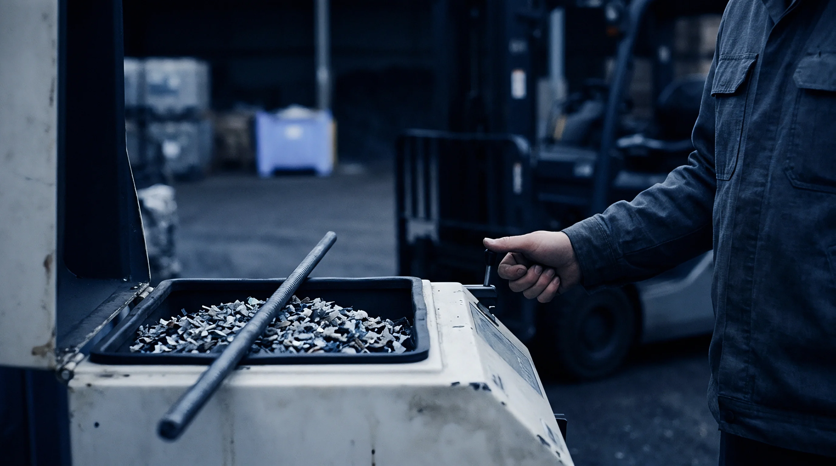
Gas-compression dieseling damages tool steel through repeated chemical attack and intense thermal cycling. Micro-cavity tips reach transient temperatures over 900 K for fractions of a second during each shot. Over hundreds of thousands of cycles, these rapid spikes cause thermal fatigue cracking ~ or heat checking ~ on critical tool faces.

Steel Degradation under Compressed Gas Discharges
Gas composition accelerates this deterioration. Ambient air ~ roughly 78 percent nitrogen and 21 percent oxygen plus moisture ~ combines at pressures above 10 MPa and extreme temperatures with volatile compounds outgassing from hot polymer. The resulting oxidative gas mixture attacks protective coatings and corrodes substrate steel.
PVD coatings like Titanium Nitride or Chromium Nitride resist mechanical wear well, but high-temperature gas micro-jets penetrate microscopic pores in the coating layer. Substrate oxidation underneath causes the coating to delaminate and flake off into micro-features, spiking demolding friction, tearing parts, and snapping ejector pins.
Selecting steel for micro-textured inserts requires prioritizing corrosion resistance. High-chromium stainless grades like 1.2083 hardened to 52 to 54 HRC or ESR-grade powder metallurgy steels withstand oxidative dieseling far better than standard pre-hardened 1.2738. Cutting high-precision micro-textures into lower-grade steel wastes capital, as the detail degrades within the first 50,000 cycles.
The cost of micro-dieseling extends well beyond mold repairs. As steel surfaces pit, release forces rise, prompting press operators to increase ejector speed and force. That leads to pin stress whitening, warped parts, and unscheduled downtime that erodes operating margins.
Suppliers who attribute part burning to resin moisture or masterbatch loading are often masking inadequate venting design in the steel.

Protocol
Procurement specifications for micro-textured molds must turn engineering requirements into binding contract terms. Purchasing precision optical, medical, or micro-fluidic tooling without explicit venting requirements leaves critical decisions to toolmaker discretion.
Commercial Tooling Safeguards for Micro-Venting
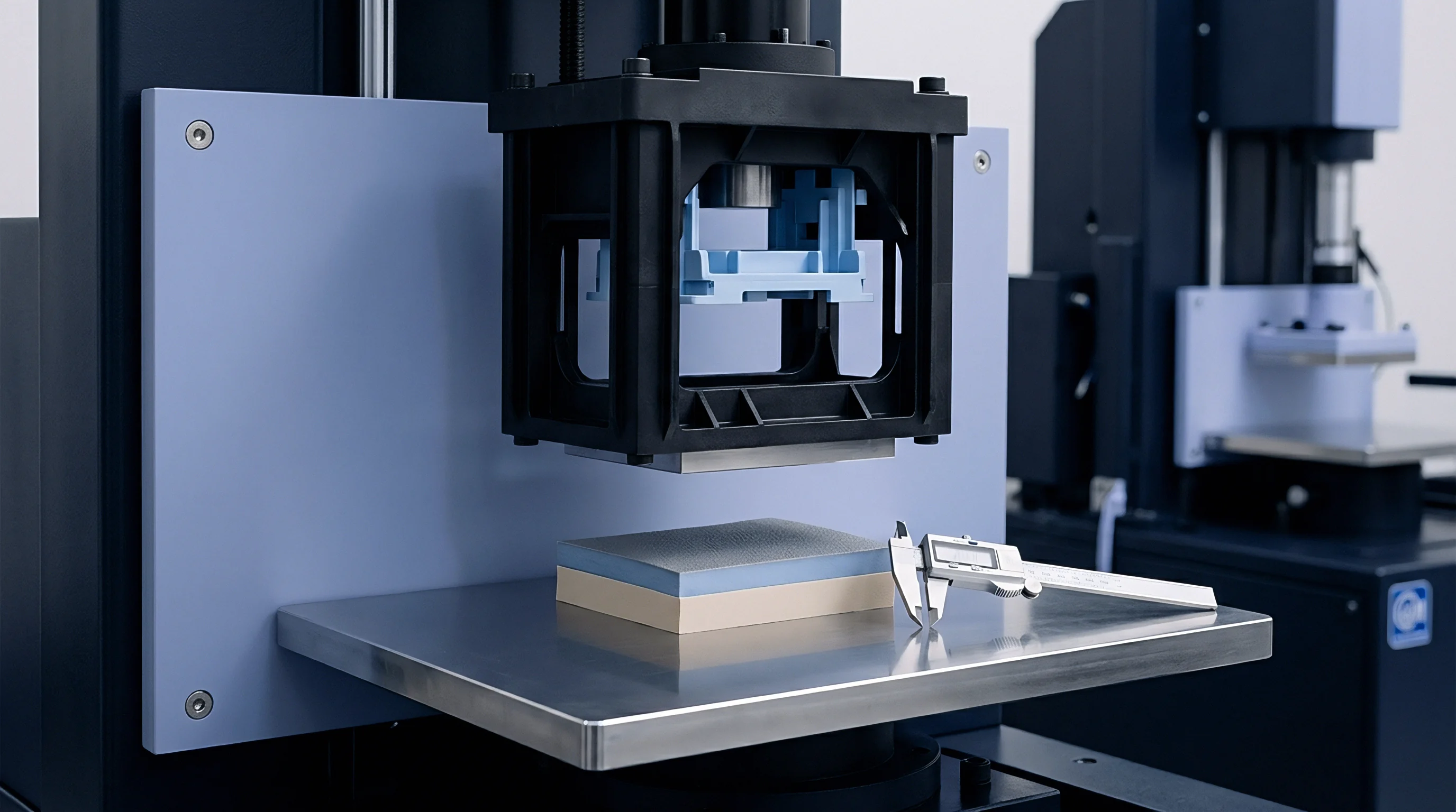
The tooling specification forms the legal basis for tool acceptance. Sourcing managers should establish explicit mechanical requirements for micro-venting before releasing tooling deposits, defining acceptable vent architectures, minimum vacuum levels, steel grades, and optical replication checks.
Toolmakers frequently omit vacuum systems from initial quotes to simplify design and reduce liability. Specifying a maximum cavity vacuum level below 10 kPa prior to injection forces suppliers to quote dynamic vacuum integration upfront, avoiding costly engineering change orders during tool sampling.
- Tool Steel Specification Clause requires ESR-melted stainless steel with a minimum of 13 percent chromium for all micro-textured inserts to prevent dieseling oxidation.
- Active Venting Clause mandates dedicated vacuum channels around micro-textured zones and requires sensor integration with the press controller.
- Permissible Defect Thresholds define soot deposit limits and mandate at least 25,000 continuous shots between scheduled mold cleanings.
- Replication Guarantee Terms tie final tooling payment to non-contact optical measurements confirming 90 percent feature height replication across all cavities.
Tool transfer terms must also account for auxiliary equipment. When relocating a mold, the receiving facility needs matching press-side vacuum controllers and ultrasonic cleaning capabilities. Without compatible hardware, even a fully qualified tool will generate scrap immediately upon transfer.
Procurement contracts that omit micro-venting validation leave buyers exposed to unrecoverable tooling costs and persistent quality disputes.
Whether gas dissolves into the melt front or remains an impenetrable cushion comes down to the microsecond pressure dynamics designed into the steel.