Meaning
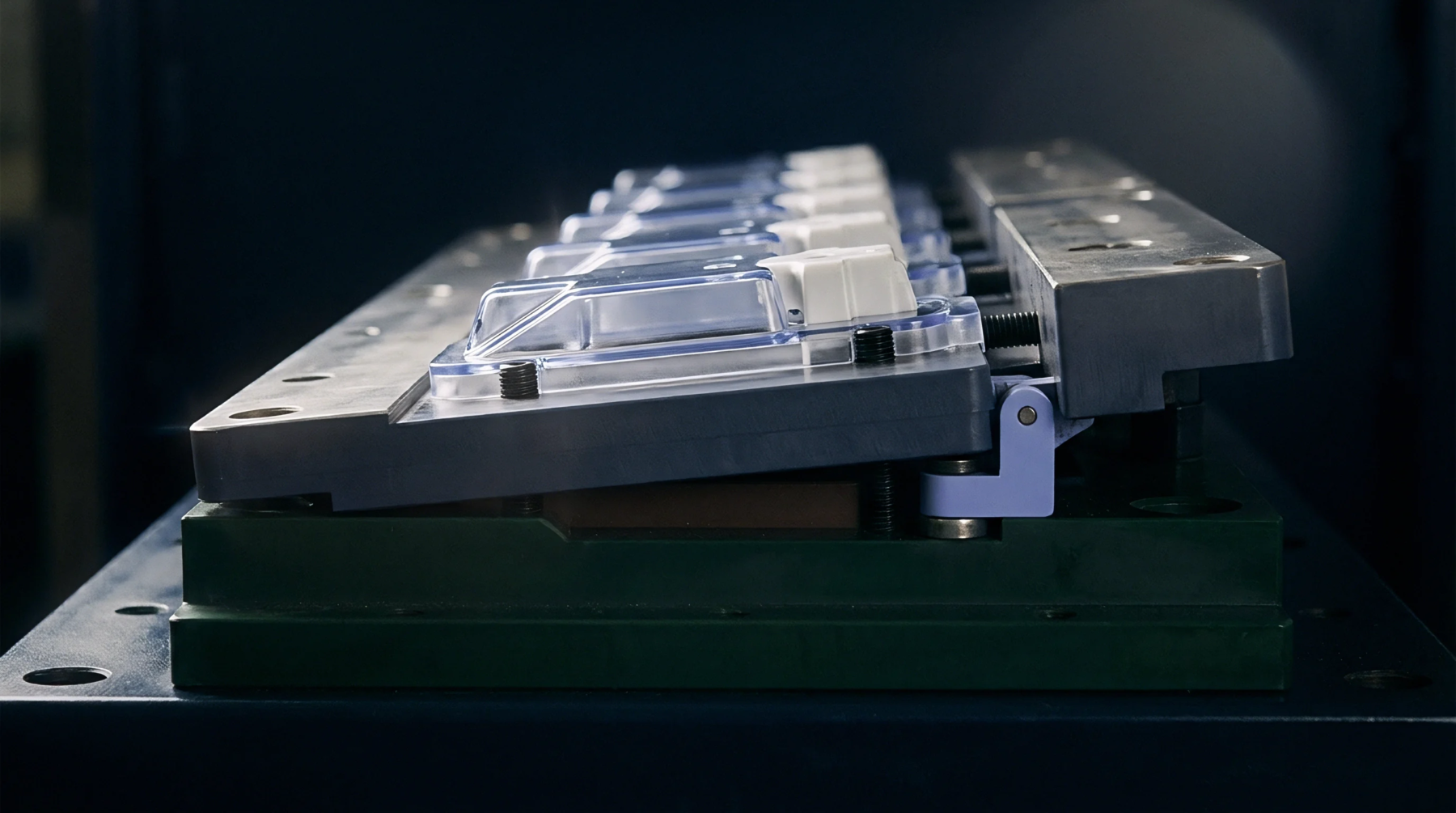
Specialized channel configurations in injection moulding tools allow air to escape from the cavity during the filling phase while preventing the passage of molten polymer. The precise dimensions of the micro-venting land geometry are engineered to match the viscosity of the specific plastic resin being processed. This layout ensures efficient gas release without causing flash defects on the part.
Geometry Structure
Optimizing the depth of the land is critical because a channel that is too deep will allow plastic to enter and create flash, while a channel that is too shallow will restrict air flow. In a typical micro-venting land geometry, the initial shallow section of the vent is very short, leading quickly into a much deeper relief channel that allows the gas to expand and escape to the atmosphere. This transition prevents pressure build up inside the mould and ensures that the vent does not become blocked by the high shear forces of the advancing melt front.
Process Performance
Air traps and burn marks are minimized when the air can escape freely from the cavity during the high speed injection phase. Correctly sized micro-venting land geometry reduces the required injection pressure and prevents the adiabatic heating of trapped gas that can degrade the polymer. This design feature allows for wider processing windows and more consistent part weight.
Maintenance Practice
Regular cleaning of the vent lands is necessary to remove the wax and outgassed residues that accumulate over time. When these deposits block the micro-venting land geometry, venting efficiency drops, leading to part defects and increased scrap rates. Simple maintenance procedures, such as wiping the parting lines with solvent during production breaks, help maintain the designed venting performance throughout the production run.