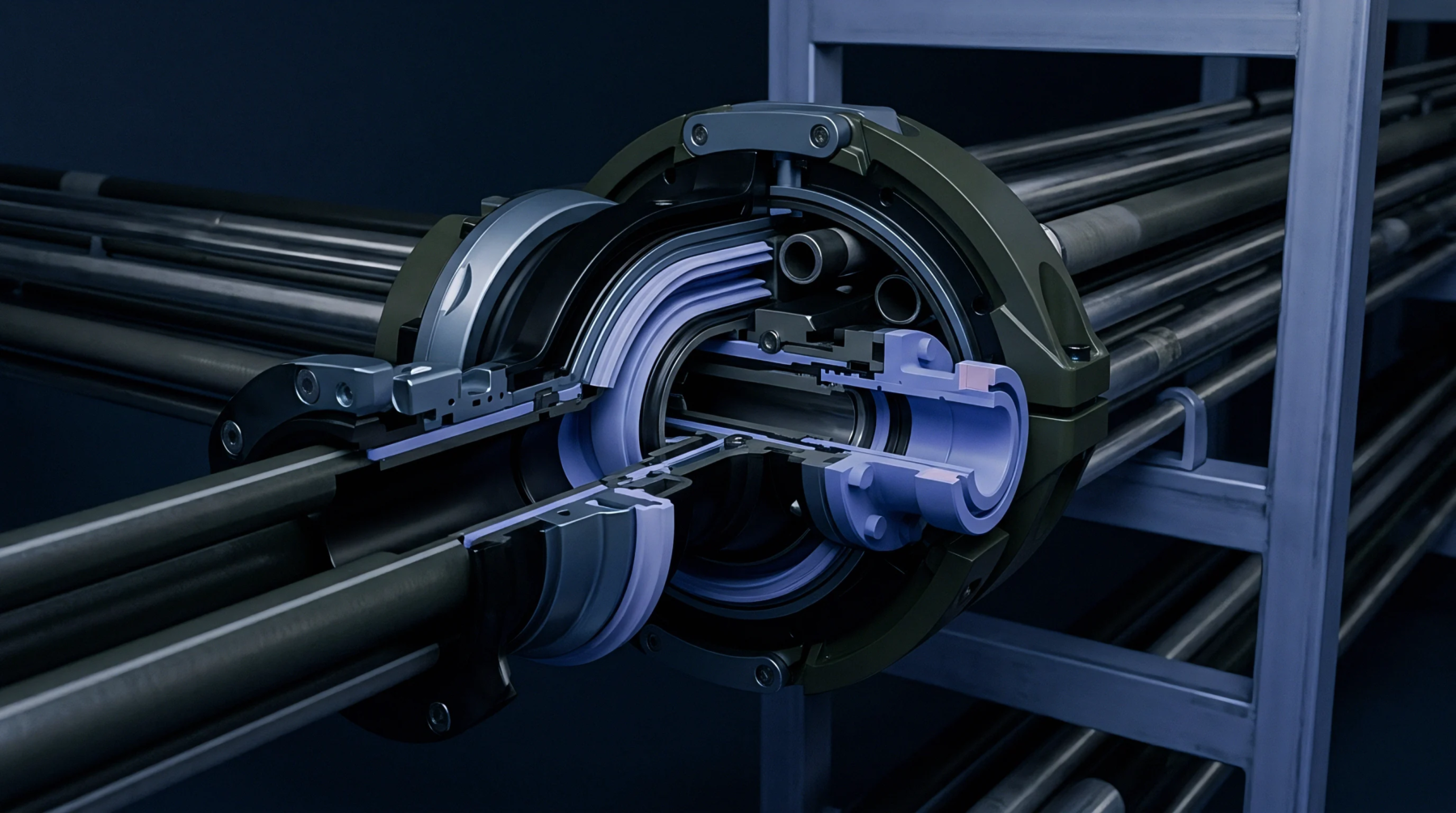
Wall Section Changes That Arrive after the Steel Is Cut
Post-cut wall section increases require steel removal that permanently alters cooling dynamics, cycle time, and dimensional stack-ups.
Radiographic imaging techniques produce high resolution three dimensional volumetric data by rotating a specimen through a stationary beam of high energy photons. Industrial ct scanning digitizes the internal density variations of complex polymer components to reconstruct non destructive slices of the entire structure. This method allows for the measurement of internal features that remain hidden from surface optical inspection.
Data gathered from these rotations informs the structural integrity of moulded items and identifies hidden voids within the core. The resolution stops at the threshold of physical beam scatter where material density renders the sensors unable to discern transitions in the resin matrix.
Volumetric data identifies trapped air pockets or thermal degradation zones that occur when cooling rates deviate from the predicted cycle. Industrial ct scanning maps these inconsistencies against the master cad model to confirm whether the wall thickness meets the structural requirements for final assembly. Excess regrind levels inside a compound alter the homogeneity of the part and show up as ghosting artifacts within the reconstructed scan.
Moulders rely on these results to distinguish between cosmetic surface imperfections and internal material failure. High precision measurements verify that the fibre orientation remains uniform throughout the geometry of the moulded part. Accurate scans prevent the cost of shipping flawed products that fail under mechanical stress during end use scenarios.
Automated software algorithms align the raw projection data into a singular voxel matrix. Industrial ct scanning transforms the raw greyscale intensities into distinct regions of interest by filtering the noise generated during the acquisition phase. Variations in scanning settings change the signal to noise ratio and determine the clarity of the interface between different material densities.
Engineers adjust the focal spot size to increase the sharpness of fine features inside the part. Lower focal spots require longer integration times for each projection which increases the total duration of the process. Stable hardware platforms reduce the vibrations that distort the reconstructed geometry during the final alignment of the image slices.
Geometric limitations arise when the material thickness or density exceeds the penetration capability of the chosen energy source. Industrial ct scanning produces artifacts around metallic inserts because the high density contrast creates photon starvation in the surrounding polymer. Scatter correction algorithms mitigate these effects but they cannot recover information lost to complete attenuation.
Correct settings ensure the scan captures the true geometry of the part rather than an artifact of the imaging process itself. Processing times vary according to the resolution requirements and the complexity of the part geometry. Accurate density mapping provides the final proof of compliance for parts manufactured under tight tolerances.
Post-cut wall section increases require steel removal that permanently alters cooling dynamics, cycle time, and dimensional stack-ups.
Expertise is a utility, not a secret. sentiention™ publishes its working knowledge as open reference: intelligence layer covering the materials it sources, the markets it enters, and the reference that serves both.