Calculating Preload Requirements to Mitigate Dynamic Platen Deflection
Calculate support column interference to generate active pre-compression exceeding peak dynamic cavity separating forces before injection switchover occurs.

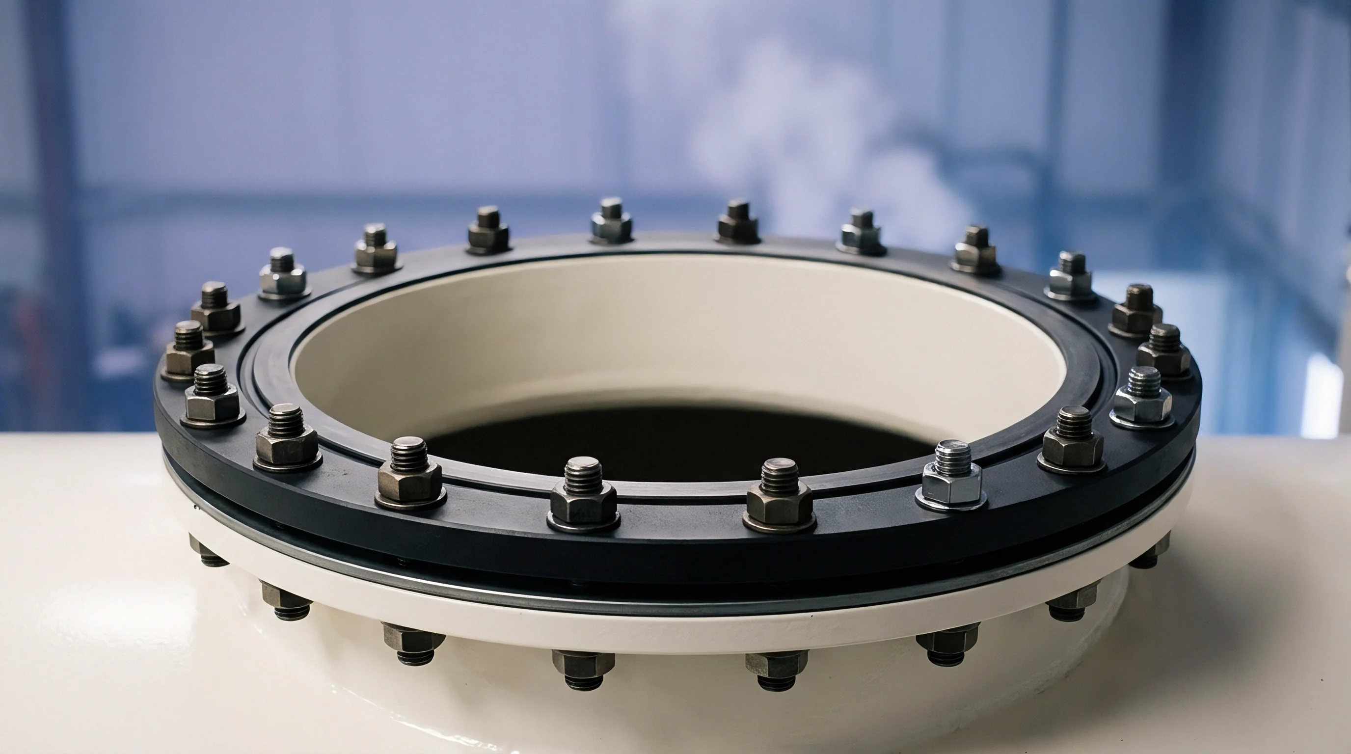
Thrust
Melt pressure peaks within twenty milliseconds. When the injection screw transitions from velocity control to pressure hold, internal cavity pressure exerts an instantaneous separating force across the parting plane. Machine clamp ratings express static hydraulic or toggle lockup capability measured across flat, rigid platens.
Injection molding tools do not behave as perfectly rigid slabs. The projected area of the cavities, runners, and sprues concentrates thousands of kilonewtons over a fraction of the platen surface. Parting line breathing begins when this transient separating force exceeds local clamping pre-compression.
Platen center spans bow outward. Standard spheroidal graphite cast iron platens exhibit elastic flexure under center-loaded tools, permitting microscopic parting line separation during peak cavity pressurization. Toolmakers calculate static clamp tonnage by multiplying projected cavity area by an average cavity pressure, adding a safety factor between ten and twenty percent.
This static calculation neglects transient pressure spikes during switchover, hydraulic inertia, and the compliance of the machine-tool stack. Clamping force opposes cavity pressure. When platen flexure allows parting line separation exceeding fifteen micrometers, low-viscosity resins flash across shutoff edges.
A mould base that relies entirely on perimeter rails flexes across its unsupported center during injection intensification.
Deflection under cyclic load degrades tooling steel and yields inconsistent part geometry across multi-cavity layouts. Platen flexure produces distinct physical defects during high-pressure cycles:
- Parting line flash escapes along parting surfaces when localized clamping pressure falls below instantaneous melt pressure during the packing phase.
- Wall thickness variation develops between center and edge cavities because center cavities breathe outward while perimeter cavities stay compressed.
- Crushed vent lands occur around the perimeter of the tool base as platen bowing transfers excessive clamping force to outside contact surfaces.
- Hobbing damage indents cavity inserts into backing plates when cyclic platen bending concentrates compressive stresses beyond steel yield thresholds.
Static clamp tonnage formulas fail because they assume uniform contact pressure across the entire parting plane. Steel compresses under load. High injection velocities intensify the hydraulic peak, producing pressure waves that travel through the melt faster than the machine clamp hydraulics can react.
Mitigating parting line separation requires calculating an active preload within the tool assembly. The press builder insists that machine platen rigidity matches published catalogue deflection charts when tested under distributed flat slabs rather than uneven tool projections.


Stack
Tooling assemblies consist of stacked steel plates held together by socket head cap screws. Clamping tonnage transfers from the machine stationary and moving platens through the top clamp plate, cavity plate, moving half backing plate, spacer blocks, and clamping flange. Every plate interface introduces contact compliance.
Machined plate surfaces exhibit microscopic asperities that compress non-linearly under load. Bolster deflection ruins part shutoffs.
Why Does Center Deflection Exceed Platen Ratings?
Machine platens possess central cutouts for ejector rods and robot clearance. These cutouts reduce the bending stiffness of the moving platen precisely where cavity separating forces concentrate. Cast iron flexes under tension.
When the ejector housing relies solely on perimeter spacer rails, the moving half backing plate spans an unsupported gap. Injection pressure forces the cavity inserts backward into this void, deflecting the backing plate toward the ejector plate.
Tie bars elongate elastically while cast platens bow around the central ejector hole pattern.
Support columns bridge the void between the moving half backing plate and the bottom clamp plate. Without adequate support column placement, backing plates manufactured from 1.2311 or P20 pre-hardened steel deflect cyclically during every injection shot. Backing plates bow toward the ejectors.
This cyclic bending induces fatigue cracks around water line cross-drills and ejector pin guide bores. Table 1 outlines calculated deflection values across typical tool plate thicknesses under standard packing pressures.
| Backing Plate Steel | Plate Thickness (mm) | Unsupported Span (mm) | Support Column Density | Center Deflection (mm) | Parting Line Breathing (mm) |
|---|---|---|---|---|---|
| 1.2311 (30 HRC) | 56 | 350 | Zero Columns | 0.084 | 0.062 |
| 1.2311 (30 HRC) | 76 | 350 | Zero Columns | 0.038 | 0.029 |
| 1.2312 (30 HRC) | 76 | 220 | Two Columns (50 mm) | 0.016 | 0.011 |
| 1.2343 (50 HRC) | 96 | 140 | Four Columns (60 mm) | 0.006 | 0.003 |
| 1.2083 (52 HRC) | 96 | 90 | Six Columns Preloaded | 0.002 | 0.001 |
Calculations based on simple beam theory underestimate plate bending because platen deformation imposes an angular boundary condition on the tool backing plate. When the machine platen dishes inward, it rotates the spacer blocks, tilting the outer edges of the cavity plate forward while allowing the center to drop. Support columns absorb clamping tonnage.
Integrating hardened support columns directly beneath cavity centers restores planar rigidity across the tool stack. Parts moulded under unresolved stack breathing suffer wall thickness drift across cavities, premature edge wear along matching shutoffs, and chronic flash that inflates deburring labour costs on every production run.

Arithmetic
Calculating the required preload begins with establishing the instantaneous separating force generated during the velocity-to-pressure switchover. Peak cavity pressures often reach seven hundred to twelve hundred bar within thin-wall automotive or connector tools. Pressure transducers record these transient values.
The separating force equals peak cavity pressure multiplied by total projected area along the parting line.
How Does Injection Impulse Alter Preload Equations?
The total separating force equation incorporates dynamic amplification factors caused by melt deceleration and machine toggle compliance. Let F_sep represent the total separating force in kilonewtons. A_proj defines the total projected melt area in square millimeters, encompassing part cavities, cold or hot runners, and sub-gates.
P_peak defines the peak cavity pressure in megapascals recorded at the gate during switchover. The dynamic impulse coefficient C_dyn accounts for hydraulic intensification spikes, ranging from 1.15 for all-electric servo machines to 1.35 for accumulator-assisted hydraulic presses:
F_sep = (P_peak A_proj C_dyn) / 1000
Tool steel behaves like a spring. To prevent parting line breathing, the tool clamping system must impart a pre-compression force F_pre that exceeds F_sep across the projected cavity footprint before injection begins. The distribution of this pre-compression force depends on the stiffness ratio between the tool support elements and the perimeter clamping rails.
Let K_col represent the total axial stiffness of all support columns, and K_rail represent the compressive stiffness of the tool base rails and outer housing. Axial stiffness follows Hooke’s law:
K = (E A) / L
Here E represents the modulus of elasticity of the column steel (210,000 megapascals for standard tool steel), A represents the cross-sectional area of the support column in square millimeters, and L represents column length between the moving half backing plate and the bottom clamp plate in millimeters. The displacement delta under clamp force F_clamp divides across the parallel stiffness network.
Peak cavity pressures exceeding eight hundred bar generate separating forces that overcome static clamp ratings by fifteen percent during hydraulic switchover.
Support column interference height creates active preload during mold closure. When toolmakers grind support columns longer than the side spacer rails, closing the mold forces the support columns into compression before the parting line lands seat completely. The required interference delta_pre relies on target pre-compression tonnage F_pre and column stiffness K_col:
delta_pre = F_pre / K_col
Evaluating this calculation requires defining the operational variables for a specific production setup:
- Target pre-compression force equals separating force multiplied by a minimum safety factor of 1.25 to prevent parting plane separation under machine platen flexing.
- Support column count determines individual column cross-sectional load, keeping compressive stress below fifty percent of the steel yield strength.
- Free column length dictates total axial compliance, where shorter risers demand tighter grinding tolerances to hold calculated preload values.
- Machine platen compliance factor modifies effective pre-compression displacement based on platen dishing charts supplied by the press manufacturer.
Take an eight-cavity connector tool running polybutylene terephthalate with thirty percent glass fiber. The projected area of cavities and runner system measures 42,000 square millimeters. Peak cavity pressure reaches 85 megapascals on a fast hydraulic press with an impulse coefficient of 1.25.
The dynamic separating force computes directly:
F_sep = (85 42,000 1.25) / 1000 = 4,462.5 kilonewtons
Applying the 1.25 safety factor sets the target preload requirement F_pre at 5,578 kilonewtons, equivalent to roughly 569 metric tons of clamp force focused beneath the cavity block. Four support columns of 70 millimeter diameter fabricated from 1.2379 tool steel (hardened to 58 HRC) yield a combined cross-sectional area of 15,394 square millimeters. With a column length of 160 millimeters, the combined axial stiffness computes to 20,204 kilonewtons per millimeter:
K_col = (210,000 15,394) / 160 = 20,204,625 Newtons per millimeter
Dividing target preload by stiffness determines the interference height grind:
delta_pre = 5,578 / 20,204 = 0.276 millimeters
Table 2 provides working design ranges for dynamic impulse coefficients and safety factors across common polymer categories under standard injection velocities.
| Resin Chemistry | Melt Flow Rate (g/10 min) | Injection Speed (mm/s) | Impulse Factor (C_dyn) | Preload Safety Margin | Maximum Breathing (mm) |
|---|---|---|---|---|---|
| Polypropylene Homopolymer | 25 (230 C, 2.16 kg) | 120 | 1.15 | 1.15 | 0.015 |
| PA66 (30% Glass Filled) | 15 (275 C, 5.00 kg) | 240 | 1.25 | 1.25 | 0.008 |
| Polycarbonate (Unfilled) | 10 (300 C, 1.20 kg) | 160 | 1.20 | 1.20 | 0.010 |
| PBT (30% Glass Filled) | 20 (250 C, 2.16 kg) | 280 | 1.30 | 1.30 | 0.008 |
| PEI (Ultem 1000) | 9 (340 C, 6.60 kg) | 220 | 1.35 | 1.35 | 0.005 |
The calculation assumes uniform temperature across the tool stack. Thermal expansion alters interference dimensions during operation. A temperature difference of twenty degrees Celsius between the moving half backing plate and the support columns changes column length by 0.038 millimeters on a 160 millimeter riser.
Tool designers integrate this thermal delta into final grinding drawings. The final clamping calculation links machine tie-bar pre-tensioning directly to the peak hydraulic pressure spike recorded at the transfer point.
Shim
Machining support columns to precise preload dimensions demands tight toolroom discipline. Surface grinding holds column lengths within five micrometers across an entire set. Support columns fabricated with loose tolerance bands fail to engage clamping tonnage simultaneously, overloading individual columns while leaving neighboring spans unconstrained.
Flash forms along the parting plane.
Toolmakers adjust support column preload height using precision ground spacer shims positioned under column mounting flanges. Laminated peelable shims lack the compressive modulus required for cyclic high-tonnage tooling; solid hardened steel shims ground from 1.2842 or gauge stock prevent settling under load. The dial indicator registers displacement.
Setting column stand-off height relies on blueing tests and physical depth micrometer mapping across the mold base before installing ejector assemblies.
Preload prevents parting line breathing. Establishing predictable support column interference follows a defined sequence in the fitting shop:
- Clean mounting pockets thoroughly to remove grinding grit, protective oil films, and burrs that introduce false compliance under initial clamp squeeze.
- Measure pocket depths using a calibrated depth micrometer across four radial quadrants relative to the tool rail reference datum.
- Surface grind column bodies in a single magnetic chuck setup to guarantee equal length across the entire production set.
- Torque retaining cap screws to specified values using calibrated torque wrenches to prevent column movement during mold cycling.
- Verify interference stand-off by mounting a dial indicator to the moving half backing plate and recording dial deflection during trial clamp squeeze on a spotting press.
Parting line relief prevents mold frame binding when platen flexure transfers clamping tonnage toward the outer tool perimeter. Toolmakers relieve parting faces outside cavity land areas by 0.50 to 1.00 millimeters, leaving narrow shutoff perimeters surrounding the cavities. Tie bars stretch under load.
Relieving non-shutoff parting surfaces concentrates available clamping force directly over cavity steel, raising local contact pressure above peak cavity melt pressure. Table 3 illustrates column interference dimensions, resulting pre-stress tonnage, and observed backing plate deflection under press lockup.
| Column Diameter (mm) | Interference Grind (mm) | Axial Column Stress (MPa) | Generated Preload (kN) | Platen Dishing Offset (mm) |
|---|---|---|---|---|
| 40 | 0.030 | 39.4 | 198 | 0.008 |
| 50 | 0.045 | 59.1 | 464 | 0.012 |
| 60 | 0.060 | 78.8 | 891 | 0.018 |
| 70 | 0.080 | 105.0 | 1,616 | 0.024 |
| 80 | 0.100 | 131.3 | 2,639 | 0.032 |
Excessive column preload causes reverse dish deformation across cavity inserts when the tool clamps shut without injection pressure present. Over-preloaded columns push cavity centers forward, concentrating shutoff landing contact on inner cavity edges. Mold faces rub during closing.
Galling ruins mirror-polished shutoffs within a few thousand cycles. Toolmakers verify that total support column pre-compression does not exceed sixty percent of machine clamping capability. Support columns belong directly behind projected cavity areas rather than grouped around ejector clearance holes.
Audit
Procuring high-pressure tooling requires verifying stack rigidity before shipping tools from the moldmaker. MOLD builders frequently omit calculated support columns to ease ejector pin layout and speed toolroom assembly. Verifying compliance demands static and dynamic inspection during factory acceptance trials.
Buyers measure platen parallelism and parting line breathing on the trial press using inductive proximity sensors or digital displacement transducers mounted across the parting plane during full-speed production shots.
Sensors track parting line movement across the entire filling and packing profile. A stable tool assembly displays less than 0.010 millimeters of parting line breathing at peak pack pressure. Breathing values exceeding 0.025 millimeters signal inadequate support column placement, insufficient plate thickness, or an undersized machine clamp.
The cavity pressure sensor triggers switchover. Dynamic displacement traces reveal whether platen bending occurs during the initial fill phase or later during hold intensification.
ISO 20457 tooling acceptance terms penalize the mould builder whenever parting line separation exceeds twenty-five micrometers during production qualification.
Factory audits verify that tool drawings specify support column interference fits, hardened column grades, and hardened stop discs beneath column bases. Platen wear profiles on older production presses must match tool spacing; deeply dished machine platens negate tool preload by bowing behind the mold clamp plates. Adding DIN 16742 tolerance group TG4 acceptance limits for parting plane steps into the purchase agreement forces the moulder to absorb tool recalibration costs when platen breathing exceeds mechanical thresholds.