Predictive Thermal Stress Modeling for Sub-Micron Optical Grating Inserts under Ultra-High Pressure Cyclic Fatigue
Predictive thermo-mechanical stress modeling balances root fillet geometry, thermal expansion matching, and pressure limits to stop sub-micron grating fatigue.
Pitch
Cavity transducers register 245 MPa of peak hydrostatic pressure while the tool interface hits 168 degrees Celsius during the packing phase of an augmented reality diffractive waveguide cassette. Tool deflection dictates optical wavefront error. Replicating a 400 nm period linear grating with a 1.2:1 aspect ratio requires the polymer melt to fill nanometer-scale cavities before vitrification locks the flow front.
Cyclic olefin copolymer at this pressure level behaves as a compressed viscoelastic solid, transferring severe mechanical shear directly against the vertical sidewalls of the optical insert ridges. Sub-micron grating inserts do not fail from uniform compression. Failure begins at the transition between the nanostructured ridge and the solid substrate plate, where local stress concentrations multiply the nominal cavity pressure by factors exceeding three.
When the toolmaker mounts a micro-machined insert into an H13 tool steel cavity pocket, the initial design challenge resides in the root radius of every individual tooth. Diamond turning and focused ion beam milling leave root fillets between 15 nm and 45 nm on high-purity single-crystal silicon or electroformed nickel-phosphorus inserts. Finite element models that treat the grating field as an idealized flat boundary conceal the true triaxial stress state.
The packing cycle imposes severe hydrostatic loads. The polymer melt forces its way into the 200 nm wide troughs, creating a bending moment on each freestanding ridge analogous to a micro-cantilever beam under distributed lateral pressure. Hydrodynamic pressure fluctuations across the runner and gate transition convert into asymmetric side loads that bend the outer teeth of each optical zone toward the perimeter.
At 240 MPa peak cavity pressure and 160 degrees Celsius variotherm cycle amplitude, the calculated von Mises stress at a 30-nanometer grating root fillet reaches 820 MPa.
The structural geometry of sub-micron optical tooling demands strict boundary containment to prevent edge-lift and corner chipping under clamp tonnage. Optical inserts for augmented reality combiner plates typically measure between 30 mm and 75 mm in diameter, with a total plate thickness between 1.0 mm and 3.0 mm. Machining tolerances on the insert pocket must stay inside 2 micrometers to eliminate micro-chatter during the injection stroke.
If the insert pocket allows lateral movement greater than 0.005 mm, the cyclic hydraulic shock causes fretting wear along the bottom ground reference face, tilting the nanostructured surface relative to the parting line.
Grating Topology and Mechanical Stress Risers
Nanoscale surface patterns alter how boundary friction translates into subsurface shear during the injection phase. The high aspect ratio of diffractive optical elements acts as an array of mechanical anchors against the shrinking polymer skin. As the melt drops through its glass transition temperature under 220 MPa to 280 MPa of holding pressure, volumetric thermal contraction generates lateral traction against the vertical facets of each nano-ridge.
The resulting shear stresses concentrate entirely within the bottom 50 nanometers of the feature root.
Micro-cracks initiate along root radii. Stress concentration factors (Kt) calculated for rectangular binary gratings with sharp corners routinely exceed 4.2 under combined hydrostatic compression and transverse demoulding drag. Introducing an intentional 25 nm root fillet lowers Kt to approximately 2.1, preserving grating integrity across extended production runs without degrading first-order diffraction efficiency.
Silicon exhibits brittle cleavage failure. In electroformed nickel-phosphorus, this concentration drives cyclic micro-plasticity, creating persistent slip bands that eventually emerge as surface fissures across the bottom of the grating grooves.
Ignoring root fillet radii during predictive finite element meshing yields non-functional optical tooling that sheds grating ridges into the scrap bin within the initial five thousand press cycles.

Coupling
Transient thermal distributions through the insert thickness introduce steep displacement differentials between the nanostructured face and the backing steel. During dynamic variotherm injection moulding, inductive or high-pressure water circuits elevate the insert surface temperature from 85 degrees Celsius to 175 degrees Celsius within 3.5 seconds, immediately followed by chilled-water quenching back to 75 degrees Celsius in 4.2 seconds. This rapid cycling generates thermal gradients across the first 500 micrometers of the insert substrate that exceed 80 degrees Celsius per millimeter.
Steel substrates expand against the insert. Because thermal diffusion rates vary widely across tooling alloys, the nanostructured surface experiences alternating states of high compressive stress during heating and tensile stress during quench-down.
| Substrate Material | Thermal Conductivity (W/m-K) | CTE (10^-6 /K) | Elastic Modulus (GPa) | Yield Strength (MPa) | Calculated Peak Fillet Stress (MPa) |
|---|---|---|---|---|---|
| Single-Crystal Silicon (100) | 148 | 2.6 | 130 | 120 | 410 |
| NiP Electroform (13 wt% P) | 38 | 12.5 | 180 | 850 | 760 |
| Binderless Tungsten Carbide | 100 | 4.5 | 620 | 2400 | 680 |
| Beryllium Copper (C17200) | 105 | 17.0 | 131 | 1100 | 920 |
| DIN 1.2343 (H11 Tool Steel) | 29 | 11.8 | 210 | 1600 | 890 |
Differential thermal expansion between the insert body and the surrounding mold base governs interfacial shear loads. Single-crystal silicon inserts present a coefficient of thermal expansion of approximately 2.6 microstrain per Kelvin, whereas the supporting H13 toolholder steel expands at 11.8 microstrain per Kelvin. Over a 100-degree thermal transient across a 50 mm insert span, this mismatch generates a theoretical unconstrained displacement difference of roughly 46 micrometers.
Copper backings dissipate heat rapidly. Rigidly bolting or brazing a low-expansion optical insert into a higher-expansion pocket generates interfacial shear stresses that exceed 280 MPa at the perimeter, causing wafer buckling or catastrophic delamination.
The calculated shear stress reaches yield. When designing floating insert mounts, the toolmaker relies on precision ground slide fits with lateral spring preloads to accommodate thermal expansion while maintaining optical centration within 3 micrometers. Thermal gradients invert during part ejection.
As the tool opens and the clamping tonnage releases, the rapid drop in contact pressure alters the thermal boundary condition instantly. Ambient convection replaces conduction into the molten part, producing a sudden thermal shock that can trigger surface crazing on brittle optical coatings.
Insert longevity doubles when the cooling transient finishes before packing pressure decay exposes the micro-ridge flanks to tensile drag.
Predictive multi-physics solvers must solve the transient energy equation alongside the mechanical equilibrium equations, passing updated nodal temperatures into the structural solver at increments no larger than 0.05 seconds. Coarse time-stepping misses the brief, five-millisecond peak in surface thermal stress that occurs precisely when the 260-degree polymer melt first touches the 165-degree insert wall under full injection velocity. Thermal skin depths in nickel-phosphorus during this contact transient are less than 70 micrometers.
Confining the temperature surge to this microscopic layer produces steep localized expansion against the cold bulk of the insert, driving the surface into immediate compressive plastic yield.
Matching the thermal expansion of the insert carrier to the optical substrate material preserves the microscopic accuracy of the tool across millions of thermal transitions.

Spall
Surface degradation under combined high-pressure packing and thermal shock manifests through micro-cleavage, coating flaking, and tip erosion. Optical waveguide tools operate in a cyclic regime where mechanical packaging pressure spikes to 260 MPa every twelve seconds while the surface layers oscillate across a 90-degree thermal band. The Coffin-Manson relationship, when modified with Morrow mean stress corrections, describes this low-cycle fatigue environment at the micro-scale.
Plastic strain ratcheting accumulates in the sub-micron ridges during each injection phase, distorting the rectangular grating geometry into an asymmetrical trapezoid that scatters incident light.

Why Do Nanoscale Grating Roots Shear Prematurely?
Shear stress localization at the base of binary optical gratings stems from the sudden cross-sectional transition between the bulk plate and the freestanding ridge. During demoulding, the solidified polymer contracts into the micro-grooves, creating an adhesive lock with static friction coefficients exceeding 0.35 against bare metallic or ceramic tooling surfaces. Ejection forces pull parallel to the optical face, exerting a strong cantilever bending moment on every ridge.
Wear manifests as rounded ridge corners. If the demoulding angle deviates from ninety degrees by more than 0.1 degree, or if platen parallelism drifts past 0.02 mm across the tie bars, the lateral stripping force shears the nanostructure clean off the substrate at the root.
- Adhesive Demoulding Pull strips sub-micron grating ridges when tool draft angles fall below one half degree per vertical sidewall.
- Hydrostatic Micro-Crushing collapses binary structures when packing pressures exceed the compressive yield threshold of the electroformed insert material.
- Thermal Ratcheting gradually flares the top crest of the grating outwards through accumulated cyclic plastic shear strain.
- Interfacial Delamination detaches anti-stick diamond-like carbon or fluoropolymer surface layers from metallic substrates under high shear transients.
Plating thickness governs compressive residual stress. For electroformed nickel-phosphorus coatings applied over copper or steel cores, residual stress within the deposit dictates fatigue life. An electroplating bath operated with improper organic brightener balances or drifting pH levels deposits nickel layers with high tensile residual stresses exceeding 150 MPa.
When superimposed onto the cyclic thermal stresses of the variotherm molding process, these built-in tensile loads cut cycles-to-failure from three hundred thousand down to fewer than twelve thousand shots. Single-crystal silicon inserts avoid plastic fatigue entirely, yet they exhibit zero tolerance for shear anomalies, shattering along crystal planes when a single cold slug passes the gate.
| Insert Material System | Residual Stress State (MPa) | Plastic Strain Range Per Cycle | Primary Failure Mode | Fatigue Limit (Cycles to Scrap) |
|---|---|---|---|---|
| Single-Crystal Silicon (111) | 0 (Stress-Free Anneal) | 0.0000 (Brittle Elastic) | Cleavage Fracture along Planes | 18,000 to 45,000 |
| NiP on H13 Tool Steel Base | +120 (Tensile as-plated) | 0.0042 (Micro-Yielding) | Root Fissuring and Tooth Spall | 35,000 to 65,000 |
| NiP with Heat Treatment (250C) | -85 (Compressive Post-Bake) | 0.0011 (Elastic Containment) | Gradual Ridge Blunting | 220,000 to 380,000 |
| WC with TiAlN PVD Coating | -450 (High Compressive) | 0.0004 (Elastic Dominant) | PVD Flaking at Feature Crests | 450,000 to 750,000 |
Finite element life prediction must incorporate damage accumulation equations that account for both mechanical strain amplitude and dwell time at peak temperature. Creep relaxation occurs within nickel coatings when holding times at 170 degrees Celsius exceed four seconds, transforming compressive peak stresses into residual tensile stresses during the cooling phase. Microstructural examination of failed inserts reveals that crack networks do not propagate downward into the tool bulk.
They travel horizontally, connecting adjacent grating roots until an entire patch of optical nanostructures lifts off as a continuous ribbon of debris.
The exact mechanism governing whether microscopic sub-surface dislocations coalesce into horizontal delamination planes or vertical shear fissures remains an open question across high-pressure optical tooling research.
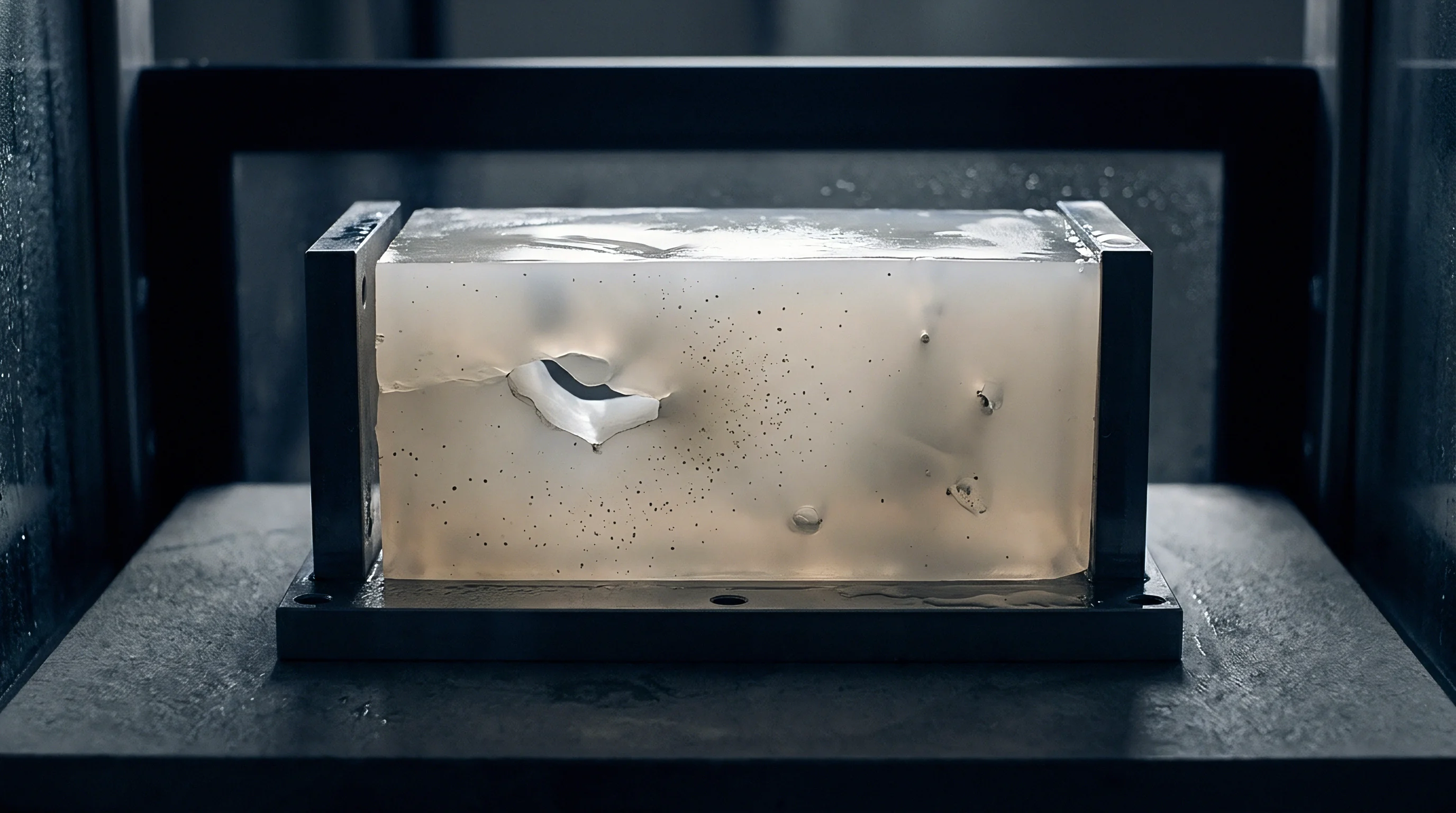
Drift
Tooling wear inside optical moulding manifests first as an invisible drop in diffractive modulation rather than a measurable dimensional shift on a hand micrometer. Process drift develops gradually across thousands of cycles as the nanometer-scale sharpness of the grating teeth degrades under thermal fatigue. Process windows shrink under tight tolerances.
On a press running cyclic olefin copolymer components, an operator might observe stable part weights, perfect cavity fill, and zero flash, while the optical verification station rejects seventy percent of output for failed diffraction efficiency and stray light scattering.
Optical diffraction efficiency drops permanently the moment plastic strain ratcheting rounds the crest of a binary sub-micron grating.
Atomic force microscopy and spectroscopic scatterometry serve as the primary diagnostic tools for detecting microscopic surface drift on the press floor. Measuring grating profiles directly off production shots provides immediate insight into the physical degradation of the tool steel. A binary grating with nominal 90-degree sidewalls and a 15 nm corner radius will begin producing optical wavefront distortion as soon as the corner radius wears beyond 45 nm.
Cavity sensors trace peak pack pressures. When the pressure curve shifts later in the cycle by even 0.08 seconds due to check-ring wear or barrel temperature drift, the melt experiences partial cooling before full pressure transmission, accelerating shear abrasion across the grating crests.
- Inline Scatterometry Mapping measures the zeroth and first-order diffracted laser beam power on every tenth moulding to identify loss of profile fidelity.
- Cavity Pressure Integral Tracking alerts the press setter whenever the area under the pack curve shifts by more than two percent across a shift.
- Non-Contact White Light Interferometry scans the master insert parting line weekly to measure localized recessing caused by cyclic clamp coining.
- Atomic Force Profilometry validates that insert sidewall angles remain within 88.5 and 91.5 degrees before signing off scheduled tool preventative maintenance.
Variations in polymer raw material rheology exacerbate tool wear patterns. Polymer resin batches with slight molecular weight distribution shifts alter the viscosity curve at high shear rates, requiring the setter to adjust injection velocity or boost pack pressures to maintain full nano-feature replication. Weld lines destroy local grating diffraction.
If melt fronts meet within a diffractive field, the localized air entrapment creates diesel-effect micro-explosions under 250 MPa, pitting the nickel insert face and etching microscopic craters into the sub-micron features within three shots.
Toolmakers often claim that periodic chemical solvent cleaning removes polymer film accumulation without affecting tool steel, yet optical profilometry confirms that repeated ultrasonic caustic washes erode nickel-phosphorus grating edges at rates exceeding two nanometers per maintenance cycle.


Audit
Capital outlays for sub-micron optical tooling require an amortisation strategy linked directly to realistic insert fatigue life rather than total mould base durability. A standard multi-cavity bolster base constructed from hardened 1.2083 or H13 steel routinely operates for several million press cycles without significant degradation. Sub-micron optical inserts fabricated via electron-beam lithography, focused ion beam milling, or single-point diamond turning carry distinct physical lifespans.
A single-crystal silicon insert cluster costs between eight thousand and twenty-four thousand dollars to fabricate, yet it exhibits a reliable operating lifespan of fewer than thirty-five thousand cycles under 240 MPa variotherm operating parameters before micro-cleavage destroys wavefront accuracy.

What Governs Insert Replacement Schedules at Volume?
Calculations for piece-part manufacturing budgets must incorporate modular tool architectures that facilitate rapid insert swapping directly at the press side. Toolmakers bill re-machined inserts separately. Running high-volume production of augmented reality lenses or micro-spectrometer gratings requires maintaining three active insert sets: one cassette running in the press, one refurbished cassette calibrated in the metrology lab, and one blank cassette undergoing diamond machining or electroforming.
If the replacement schedule is misaligned with the fatigue life predicted by thermal stress modeling, the moulder risks catastrophic insert failure mid-run, resulting in extensive press downtime, ruined multi-cavity bolsters, and lost shipments.
| Insert Technology | Initial Set Cost (USD) | Fatigue Life Limit (Shots) | Refurbish Cost Per Cycle (USD) | Tool Cost Allocation Per Lens (500k Run) |
|---|---|---|---|---|
| E-Beam Silicon Master (Direct Tool) | $18,500 | 25,000 | $12,000 (New Fab) | $0.485 |
| NiP Electroform Shim (Replaceable) | $6,200 | 180,000 | $2,100 (Re-plate) | $0.021 |
| Diamond-Turned OFHC Copper Insert | $9,400 | 85,000 | $3,800 (Re-cut) | $0.054 |
| Tungsten Carbide with PVD Film | $32,000 | 600,000 | $7,500 (Strip/PVD) | $0.064 |
Consider an operational production scenario for an optical combiner lens: a two-cavity tool running on an eight-second variotherm injection cycle yields 900 shots per hour across an eighty-hour production week. Under these conditions, a tool set with an insert fatigue limit of 65,000 shots reaches its mechanical wear threshold in roughly three weeks of steady production. If the procurement contract fails to establish who finances scheduled insert replacement, the supply chain stalls the moment optical diffraction yields drop below commercial specifications.
Tooling ownership clauses must distinguish clearly between the durable mould base and the consumable micro-structured inserts.
Section 4 of SPI Tooling Standards assigns financial liability for consumable cavity inserts directly to the buyer when production volumes exceed the verified mechanical fatigue limit of the nanostructured substrate.
Every manufacturing supply agreement for diffractive optics must stipulate cavity pressure limits, maximum variotherm thermal ramping rates, and certified metrology baselines for insert retirement. When process parameters wander outside the predictive modeling envelope, resulting in premature mechanical fatigue, documented press-side transducer logs determine whether the tooling invoice falls to the moulder or the component buyer.