Meaning
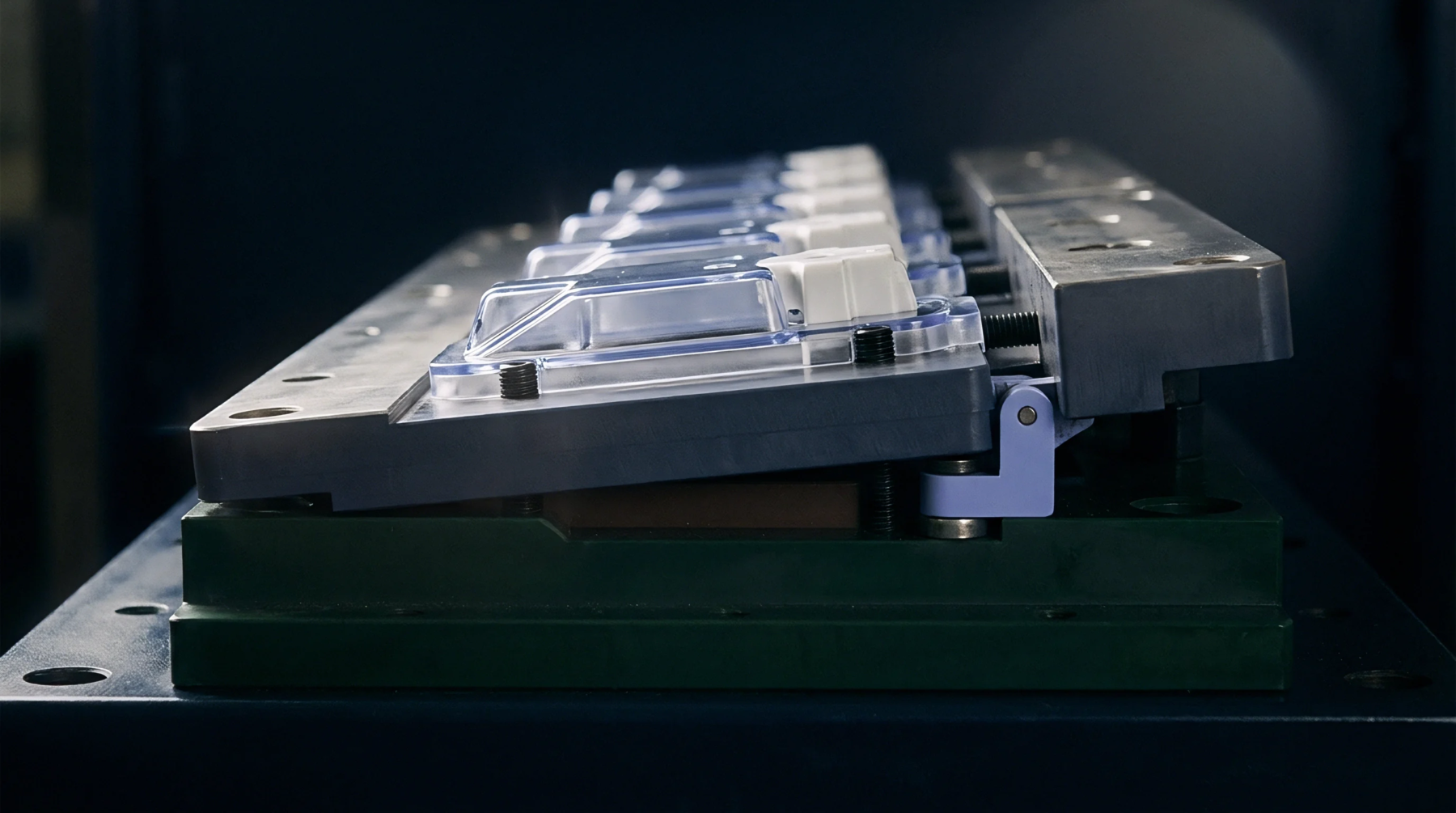
Geometric tool taper constraints establish the minimum allowable cavity wall clearance required to eject clear plastic optical components without scuffing. Adhering to optical draft angle limits prevents micro-scratching on polished lens surfaces and transparent displays during demoulding. Clear polymers like polycarbonate require larger tapers than opaque resins because surface scratches degrade optical transmittance.
The boundary ends where flat optical faces lie perpendicular to the mold opening axis and require no side wall taper.
Light Transmission
Wall tapers alter the reflection and refraction angles of light rays passing through moulded optical components. Setting strict optical draft angle limits balances demoulding capability against strict photometric performance specifications. Excessive tapers alter lens thickness profiles and create unwanted light distortion.
Insufficient tapers force core dragging, causing vertical haze lines that scatter light.
Tool Design
Mould designers incorporate precise draft angles into core and cavity CAD models based on resin shrinkage and surface polish grade. Calculating optical draft angle limits guides toolmaker decisions regarding side-action cores and ejection pin placement. Highly polished mirror inserts reduce friction, allowing lower tapers than matte surfaces.
Correct draft selection prevents high ejector force requirements that stress clear mouldings.
Scuffing Control
Demoulding friction against steep sidewalls creates visual blemishes and haze on transparent parts.