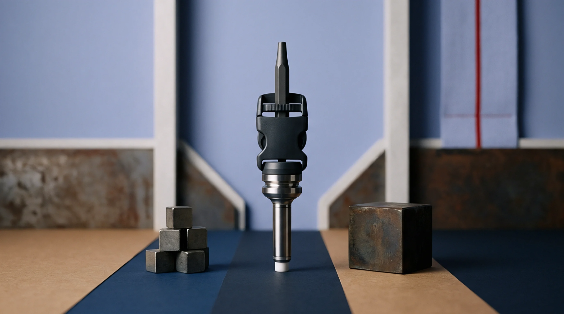
Thermal Expansion Mechanics in High Cavitation Micro Injection Tooling
Precision thermal pitch compensation and strict alloy CTE matching eliminate alignment failures and shut-off land galling in high cavitation micro tooling.
Cavity geometry variance defines the physical deviation of mould dimensions resulting from local heat fluctuation during the injection phase of polymer processing. Thermal pitch drift represents a deviation where internal mould spacing shifts between shot cycles because of unequal cooling rates or heating element instability. This phenomenon alters the distance between core and cavity features, preventing precise registration of parts that require tight tolerance alignment.
When thermal pitch drift occurs, the mechanical integrity of the final moulded unit suffers as positional accuracy fails across multi-cavity layouts. Specifications for material density or viscosity rarely account for this spatial instability, which remains a function of tooling thermal management rather than raw polymer chemistry. The boundary of this concept lies within the mould hardware and the process controls that regulate heat exchange.
Operators monitor the dimensional stability of high precision parts through the lens of internal cavity positioning. Thermal pitch drift complicates the production of micro components that require perfect alignment across all injection points. Moulders rely on cooling channel design and uniform heater distribution to mitigate the risks associated with uneven expansion of the metal substrate.
Proper cooling cycle timing helps maintain a constant temperature gradient across the tool face. This stability keeps the mechanical pitch consistent during high volume production runs. Virgin resins often exhibit different shrinkage behaviours compared to regrind mixtures, which adds complexity to maintaining the intended distance between features.
Technical staff often compare the actual part measurements against a master reference to detect shifts. A stable thermal environment minimizes the risk of geometric deformation in sensitive polymer assemblies.
Injection pressure and melt temperature govern the primary energy input into the moulding system. Thermal pitch drift arises when the cumulative heat load exceeds the capacity of the cooling circuit to return the tool to its baseline state before the next cycle initiates. Excessive cycle speed exacerbates the mismatch between thermal expansion and contraction cycles of the steel plates.
Every additional degree of heat gain alters the effective pitch of the mould components. This modification produces a drift that persists until the operator slows the cadence or adjusts the coolant flow rate to balance the system. Precision settings on the machine cannot compensate for a physical shift in the tool itself.
Part rejection rates rise when the pitch accuracy falls outside the permitted tolerance window. Scrap costs accumulate rapidly because the defect often occurs in high density moulds where every cavity contributes to overall yield. Tooling maintenance programmes must address the degradation of thermal conduits to prevent early failure of high precision production cycles.
Companies account for these losses by incorporating buffer cycles or using secondary cooling systems to stabilize the environment during peak operation hours. A mould that exhibits thermal pitch drift represents a risk to long term manufacturing efficiency that simple speed increases fail to rectify.
Precision thermal pitch compensation and strict alloy CTE matching eliminate alignment failures and shut-off land galling in high cavitation micro tooling.
Expertise is a utility, not a secret. sentiention™ publishes its working knowledge as open reference: intelligence layer covering the materials it sources, the markets it enters, and the reference that serves both.