Meaning
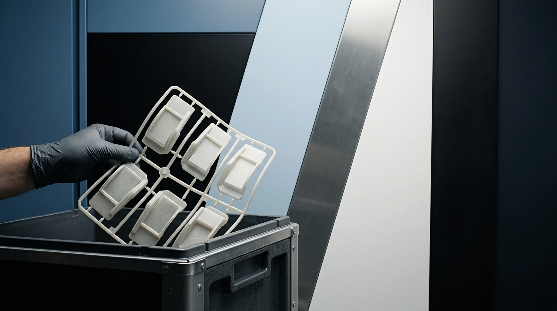
Feed system configurations arrange mold cavity impressions in a circular pattern centered on a central sprue source. Employing a radial runner layout provides equal runner length and volume to every gate without secondary or tertiary branching networks. This layout applies to circular molds with low cavity counts, typically four, six or eight impressions, but becomes impractical for rectangular mold base standards.
Flow Equidistance
Identical channel lengths from sprue to gate yield identical flow resistance. Utilizing a radial runner layout delivers resin to all cavity gates simultaneously.
Thermal Distribution
Circular arrangement of flow channels creates isotropic thermal gradients outward from the central sprue location. Designing with a radial runner layout minimizes resin dwell time variations because every fluid stream travels the exact same path length through identical thermal zones. Amorphous resins like poly-methyl methacrylate benefit from this thermal symmetry, showing reduced optical birefringence and lower residual stress levels across all cavity impressions.
The primary limitation stems from plate space usage, as circular cavity arrangements leave unused steel near rectangular mold plate corners. When processing high-cost engineering polymers, the enlarged runner cold slug volume produced by wide radial arms increases material scrap expense unless closed-loop regrind regranulation is utilized.
Tool Space
Round cavity arrays demand specialized circular water cooling channels to match heat extraction with runner geometry. Implementing a radial runner layout requires custom cooling line drilling that follows the perimeter of the cavity ring. Uniform thermal management across the circular cavity array prevents localized mold hot spots and reduces part warpage.