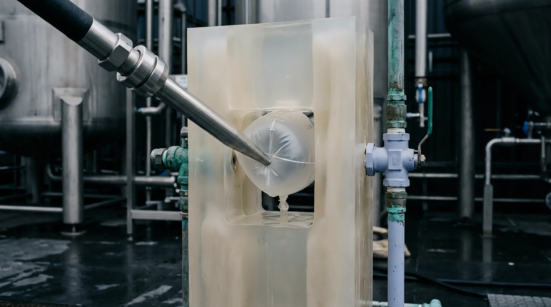
Micro Mould Cavity Pressure Sensor Placement Mechanics
Sub-millimetre cavity pressure sensor placement requires sub-two-micron pin clearances and end-of-fill installation to decouple micro-melt viscosity from V/P switchover.
Mechanical load transfer components provide the physical link between hydraulic ejection actuators and the internal surfaces of a mould cavity to enable the systematic removal of solidified polymer shapes. The force transmission pin carries high kinetic loads during the stripping phase of an injection cycle to ensure the part ejects without deformation. This hardware maintains a strict tolerance against the bore of the mould base to prevent flash while supporting the cyclical stress applied by the press hydraulics.
Proper alignment prevents the galling of the hardened steel interfaces and keeps the ejection pressure uniform across the projected area of the plastic component. Its physical dimensions dictate the maximum pressure a moulder can apply before the steel interface risks permanent deformation.
Efficient operation of a force transmission pin relies on the exact synchronization of the ejection stroke speed and the hardening depth of the alloy material. Rapid pressure spikes during the initial phase of part removal can cause buckling if the stem diameter remains too small relative to the cross-sectional area of the moulded part. These components move through precision-bored sleeves that demand frequent lubrication to offset the high friction generated by glass fiber reinforced resins.
Friction levels fluctuate based on the resin temperature and the packing pressure held during the cooling phase of production. Engineers choose specific surface treatments like nitriding or chrome plating to reduce the coefficient of friction and improve the wear resistance of the contact points.
Moulding facilities must distinguish between the design intent of the force transmission pin and the limitations imposed by regrind content in the feed. Virgin resins exhibit predictable shrinkage rates that allow the pin to function within calculated tolerances during continuous operation. High levels of regrind alter the viscosity profile of the polymer and increase the ejection force required to clear the part from the core.
Excessive force leads to pin deflection which creates uneven pressure distribution and premature failure of the tooling structure. A datasheet value for tensile strength rarely predicts the actual behavior of the metal under the thermal cycling seen during high volume production runs. Tooling shops select hardened H13 or similar alloys to ensure the component maintains its geometry despite repeated exposure to high mould temperatures.
Catastrophic seizure of a force transmission pin arises when the thermal expansion coefficient of the pin material exceeds that of the surrounding sleeve assembly. Persistent misalignment results in excessive heat buildup at the interface and creates permanent scoring of the cavity floor. Damage to the part surface usually occurs because the pin bends under pressure rather than maintaining its perpendicular axis against the plastic.
Any deviation from the prescribed hydraulic sequence risks a complete mechanical lockout of the ejection system. Production downtime remains the primary cost consequence of a compromised pin geometry. Proper preventative maintenance schedules based on cycle counts keep these critical components operational across extended manufacturing runs.
Sub-millimetre cavity pressure sensor placement requires sub-two-micron pin clearances and end-of-fill installation to decouple micro-melt viscosity from V/P switchover.
Expertise is a utility, not a secret. sentiention™ publishes its working knowledge as open reference: intelligence layer covering the materials it sources, the markets it enters, and the reference that serves both.