Meaning
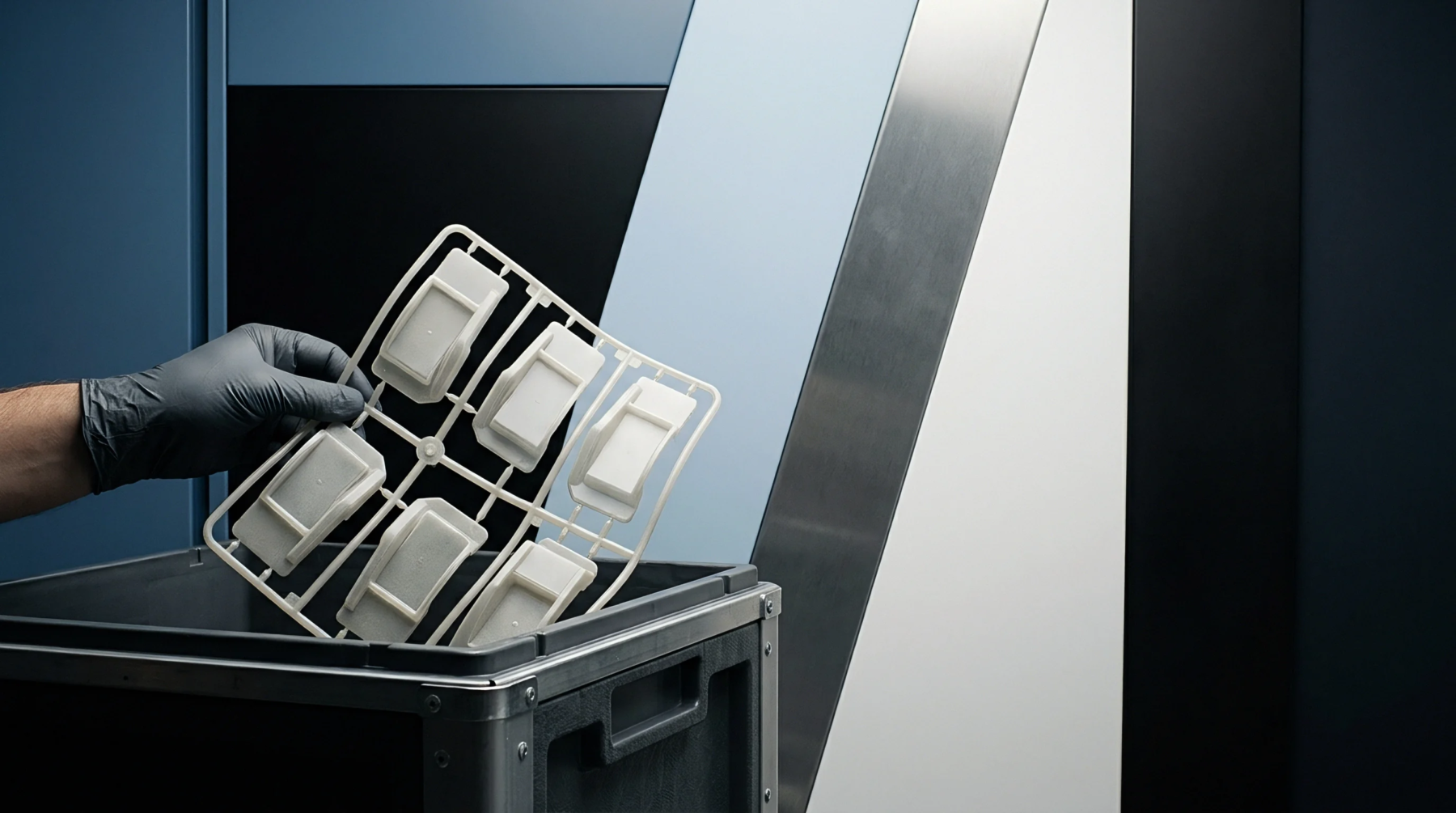
Technical documentation utilizes specific geometric annotations to define physical tolerances, material finishes, and dimensional requirements for manufactured components. These drawing callouts provide the link between the static design file and the mechanical performance of a finished injection moulded part. They mandate the absolute limits for critical features like wall thickness, draft angles, and hole diameters during the production cycle.
Designers place these markers on blueprints to constrain the variance of polymer flow and shrinkage that occurs inside a mould cavity.
Processing Limits
Injection moulding operations rely on these constraints to establish the acceptable range for cavity pressure and melt temperature during mass production. If the designated tolerance on a wall thickness dimension drifts beyond the indicated value, the resulting part experiences uneven cooling and internal stress accumulation. Production teams adjust holding pressure or cooling cycle duration to keep the actual part geometry within the bounds defined by the drawing callouts.
Regrind material usage often fluctuates based on the strictness of these dimensional requirements, as high levels of recycled polymer increase the instability of final part dimensions compared to virgin resin performance.
Constraint Logic
Tooling designers translate every specific annotation into physical mould steel dimensions, factoring in the anticipated shrinkage rate for the chosen thermoplastic grade. Failure to respect these instructions during the initial machining of the mould leads to high scrap rates or the necessity for expensive tool rework. The accuracy of the final geometry remains the primary metric for verifying that the manufacturing process adheres to the original design intent.
Compliance Verification
Dimensional inspection methods quantify how well a moulded batch aligns with the provided annotation requirements. Sensors or manual measurement tools capture the actual width or position of features and compare them against the permitted deviations. Proper application of these standards ensures that the final part fits into its intended assembly without interference or structural weakness.